84 Chapter 3
Troubleshooting the RF Section (E4440A, E4443A, E4445A)
RF Section Description (E4440A, E4443A, E4445A)
The remaining biases are 2
nd
_LO_PIN and 2
nd
_LO_ATTEN. Since
these are currents they cannot be directly measured at the Lowband
assembly connector. The output of the DAC which controls this ALC
circuit on A13 is A13TP25. To help verify that this part of the circuitry
which drives the Lowband assembly is functioning correctly, perform
the 2
nd
LO Power adjustment.
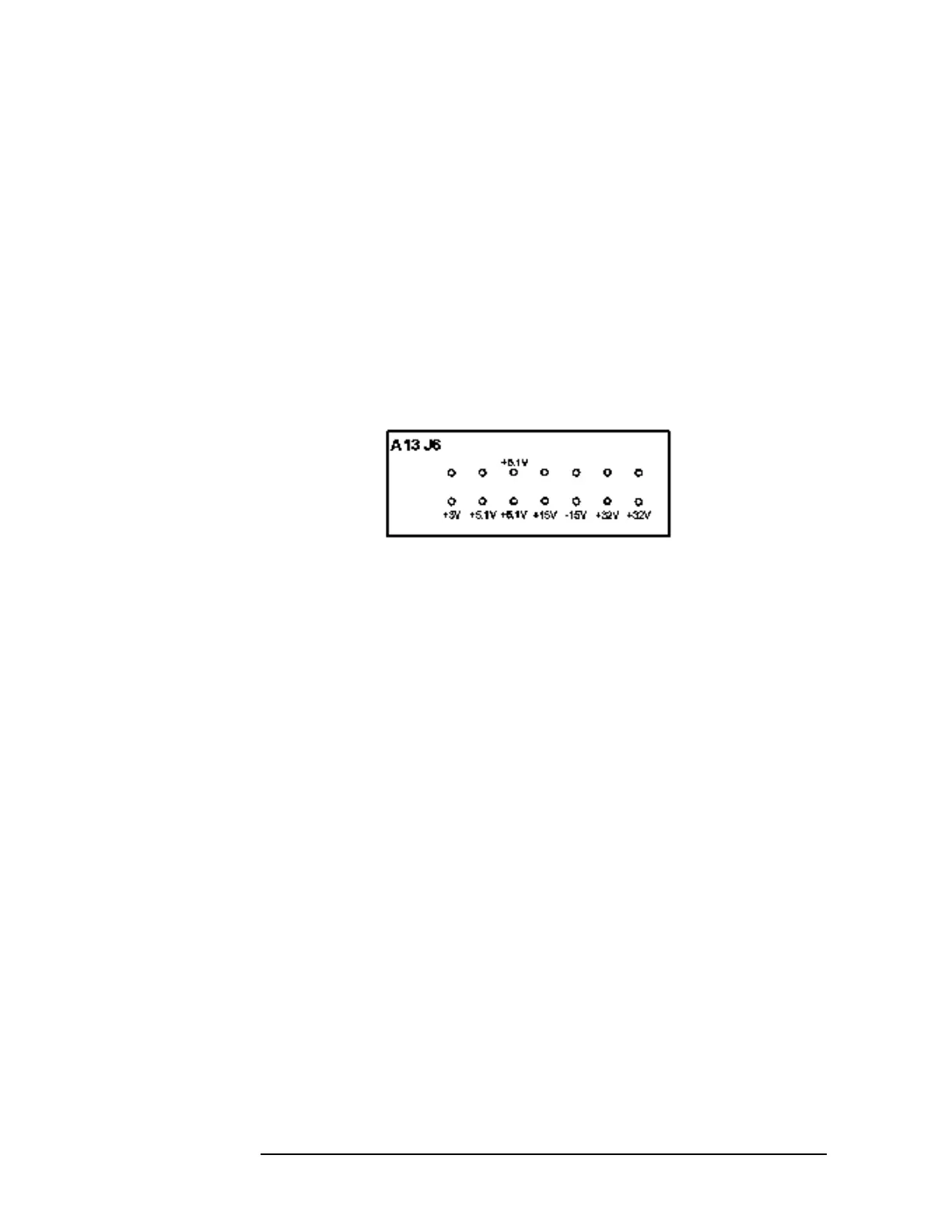
A13 Front End Driver
The Front End Driver assembly contains the circuitry needed to drive
the microcircuits and other assemblies used in the RF section. Many of
these circuits can be verified using the previous discussions for
verifying these assemblies. The voltage values on selected connectors
are (with ground connection on A13TP16 top of board near fans):
Option 219, Noise Figure, provides a switched 28V (via A13J14) to the
rear panel to drive a noise source. Press
System, Service, enter the
password −49, and press
Service, Noise Source to turn on the 28V at
J14. This 28V is the result of regulating the +32V power supply voltage
on the Front End Driver assembly. If the 28V cannot be turned on or is
not 28V ± 0.2V, suspect the Front End Driver or a power supply
problem. The RF input attenuator also uses the +32V supply, so if the
attenuator also functions incorrectly, suspect an incorrect power supply
level.
Option AYZ, External Mixing, requires the front end driver to switch
the input signal path on the A10 3
rd
converter and provides the
preselector tune out range to the rear panel. The preselector tune out is
required to tune the tracking filter on the Agilent 11974 series
preselected mixers.
The LO leveling circuit and LO Unlock Sense circuits are on this
assembly.
 Loading...


