356 Chapter 11
Assembly Replacement Procedures
RF Section E4446A, E4447A, E4448A
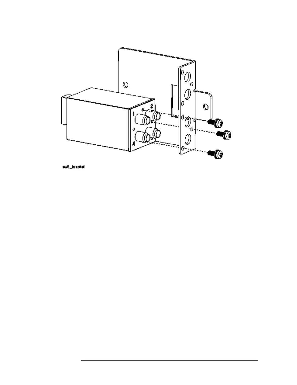
Figure 11-34 SW5 and Bracket
Replacement
1. Attach SW5 to the bracket using the three screws removed earlier.
Torque to 6 in-lbs.
2. Place the switch/bracket assembly into place on the main bracket.
Refer to Figure 11-31. Replace the two screws (2) that attach the
SW5 bracket to the main bracket. Torque to 9 inch-pounds.
3. Replace cables W99, W100, and W105. Torque to 10 inch-pounds.
4. Replace ribbon cable W92.
5. Replace the front frame.
 Loading...


