Do you have a question about the Aim STANAG3910 and is the answer not in the manual?
Overview of the ANET3910-EN module and its capabilities, functions, and architecture.
Lists industry and product-specific documents referenced within this manual.
Describes the installation process for the Board Support Package (BSP) software.
Instructions for connecting the external power supply and hardware interfaces.
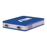
Details the front and back panel connectors of the ANET3910-EN module.
Describes the 15-pin DSUB connector for the STANAG3838/MIL-STD-1553 bus.
Describes the 9-pin DSUB connector for the electrical STANAG3910 bus.
Details the 15-pin DSUB auxiliary connector for I/O signals.
Describes the USB Type-A host connector for storage or WLAN.
Describes the DC power input connector and nominal input voltage.
Describes the standard RJ45 Ethernet connector for network connection.
Explains the LED indicators for module power and status.
Describes the Link/Activity and speed detection LEDs on the RJ45 connector.
Explains the status indicated by the illuminated AIM Logo LED.
Instructions on how to power the module on and off using the push-button.
Lists browser requirements for configuring the ANET3910-EN via web application.
Describes how to attach ANET3910-EN modules to an IPv4 network.
Steps for network integration when the network provides a DHCP server.
Steps for network integration when no DHCP server is available.
Explains how to use the AIM Network Detection Tool to find modules.
Guide to installing Apple Bonjour for zero-config network detection.
Instructions on how to operate the AIM Network Detection Tool.
Overview of module configuration performed via a web browser.
How to set alias name and change password in the web interface.
Configuring static or dynamic IP addresses and network routes.
Steps to configure Wi-Fi connection including Mode, ESSID, and Security.
How to configure running services like SSH and ANS1553.
Shows GPIO states and configuration in the web interface.
How to access and view system log files from the Maintenance tab.
Rebooting or shutting down the module over Ethernet.
How to reset the module to its factory default settings.
Steps to update the module's software or firmware.
Details the FPGA/SoC components including cores and processors.
Describes the shared SSRAM memory used by processors.
Details the Low Speed Bus Interface (LS BIU) logic.
Describes the STANAG 3838 Manchester encoder.
Describes the STANAG 3838 Manchester decoder.
Details the High Speed Bus Interface (HS BIU) logic.
Describes the STANAG 3910 Manchester encoder.
Describes the STANAG 3910 Manchester decoder.
Overview of the physical I/O interface and channels.
Explains MILbus coupling modes like Isolated, Transformer, and Direct.
Details the electrical STANAG3910 High Speed transceiver.
Lists electrical specifications for the STANAG3910 interface.
Illustrates the general structure of an electrical STANAG3910 HS-Bus.
Describes the eight user-definable discrete I/O signals.
Details the Application Support Processor (ASP) and its functions.
Explains the Time Code Processor functions (Encoder/Decoder).
Describes the IRIG-B compatible time code processor.
Explains connection methods for time tag synchronization.
How to find the device's IP address using the network detection tool.
Troubleshooting steps for device visibility issues in the network.
Procedure to reset the password using the emergency boot button.
Troubleshooting module boot loop issues using emergency mode.
Steps to resolve application connectivity issues to the device.
Details of various memory types (RAM, SSRAM, Flash, EEPROM).
Information on the 10/100/1000Mbit/s Ethernet interface.
Information on the dual core RISC processors.
Technical specifications for the STANAG3838 Encoder.
Details on error injection capabilities for STANAG3838.
Technical specifications for the STANAG3838 Decoder.
Technical specifications for the STANAG3910 Encoder.
Technical specifications for the STANAG3910 Decoder.
Details of the MIL-STD-1553/STANAG3838 physical interface.
Electrical characteristics of the STANAG3910 interface.
Information about the IRIG-B time code processor.
Lists all physical connectors on the back and front panels.
Describes the Power ON/OFF and Emergency Boot buttons.
Specifications for the TTL compatible Trigger Input.
Specifications for the TTL level Trigger Output.
Details on input/output voltage and current for discrete signals.
Input voltage range for the module.
Operational power consumption details for the module.
Standard and extended operating temperature ranges.
Humidity operating range for the module.
Physical dimensions of the module.
The weight of the module.
Glossary of acronyms and abbreviations used in the manual.
Describes the back panel adapter for table operation.
Steps to connect the ANET Table Adapter to the module.
Details on volatile and non-volatile memory contents.
| Brand | Aim |
|---|---|
| Model | STANAG3910 |
| Category | Control Unit |
| Language | English |