ANET3910-EN User’s Manual
4.5.3 Discrete I/Os
The ANET3910 module provides eight user definable discrete I/O signals. Discrete input
signals are always active whereas the discrete output signals are per default inactive.
An open collector circuitry is used for the discrete output with approximately 4V
provided by default. An external voltage from 0 to 35V can be supplied externally for
switching higher voltages.
Please Note:
The discrete outputs don’t provide a series resistor for over current protection. In case a
discrete input is used, make sure that the output-mode for that discrete is disabled,
before connecting an external voltage, otherwise a high short circuit current to GND can
damage the output transistor.
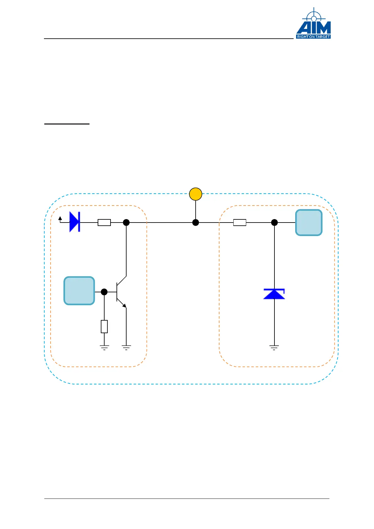
Figure 4-5 Discrete I/O circuitry
Be aware that a series resistor must be provided when a user voltage is used. This
serial resistor must limit the current through the open collector transistor to max. current
(see technical data chapter for details). Otherwise the open collector transistor can be
damaged. EMC aspects are covered by filter circuitry.
Discrete IO-Pin Front Connector
Resistor
limiting
Resistor
(1 KΩ)
limiting
Resistor
Discrete output circuitry