ANET3910-EN User’s Manual
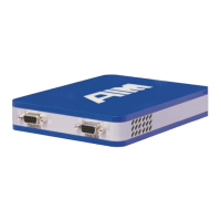
1
6
5
9
(front view)
9 Pin DSUB (female)
Note:
The Aircraft-GND is galvanic de-coupled from the ANET3910-EN on board GND, it ends
at the primary side from the 3910 electrical transformer.
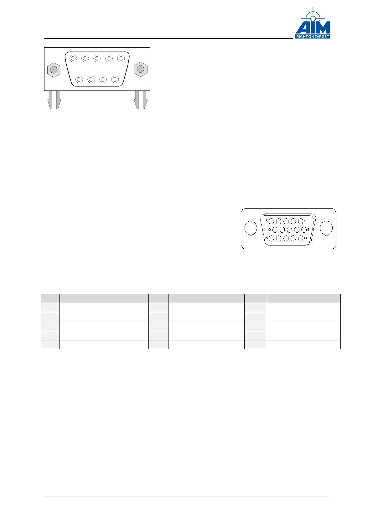
2.2.1.3 Auxiliary Connector HD DSUB15
On the ANET3910-EN a 15-pin female High Density
DSUB auxiliary connector is implemented for the Trigger
IN/OUT, IRIG IN/OUT and Discrete I/O signals.
The figure on the right side shows the high density
DSUB connector.
The Table below shows the pin assignment.
A description of the Trigger IN/OUT, IRIG IN/OUT and the Discrete IOs can be found
later in this document.
Table 2.2.1.3-2 Pinout Auxiliary Connector
2.2.1.4 USB TYP-A Host connector
A TYP-A host USB connector is provided e.g. for connecting external storage devices or
an optional WLAN stick.
Figure 2-5 Auxiliary Connector (front view)
Figure 2-5 DSUB9 (front view)