4. Structure of the ANET3910-EN
4.5 Physical I/O Interface
Consist of a Dual redundant STANAG-3838/ MIL-STD-1553B (Low Speed) channel with
programmable output Amplitude and Coupling Network and a dual redundant 3910
(High Speed) Fibre Optic channel.
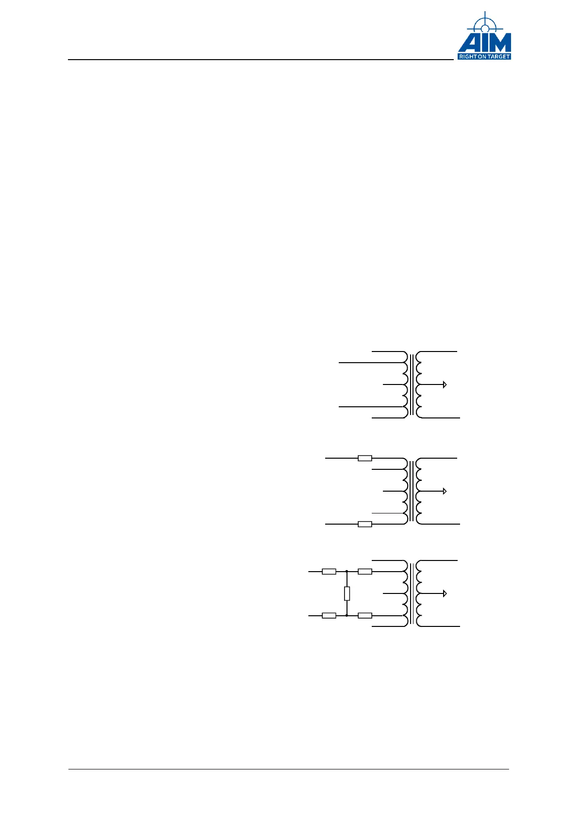
4.5.1 Low Speed Physical Interface & Coupling Modes
One dual redundant STANAG-3838/ MIL-STD-1553B interface is available, which
implements a MILbus Transceiver with variable output amplitude capability. Further on,
the Low Speed Bus Frontend implements programmable coupling network with
following coupling modes:
Interface Connector (Bus
Side)
ANET3910-EN (Transceiver
side)
No connection to the MILbus
Transformer Coupled with
Network Emulation
IN
/IN
SH
LG
/LG
/SH
23R
23R23R
23R
23R
The following figure shows the Low Speed Bus output amplitude (on a 70Ω Bus
Termination @transformer coupled mode) over the full amplitude range. The Amplitude
can be controlled by the user via the Software API Function (ApiCmd….).
Figure 4-2 Coupling modes