ANET3910-EN User’s Manual
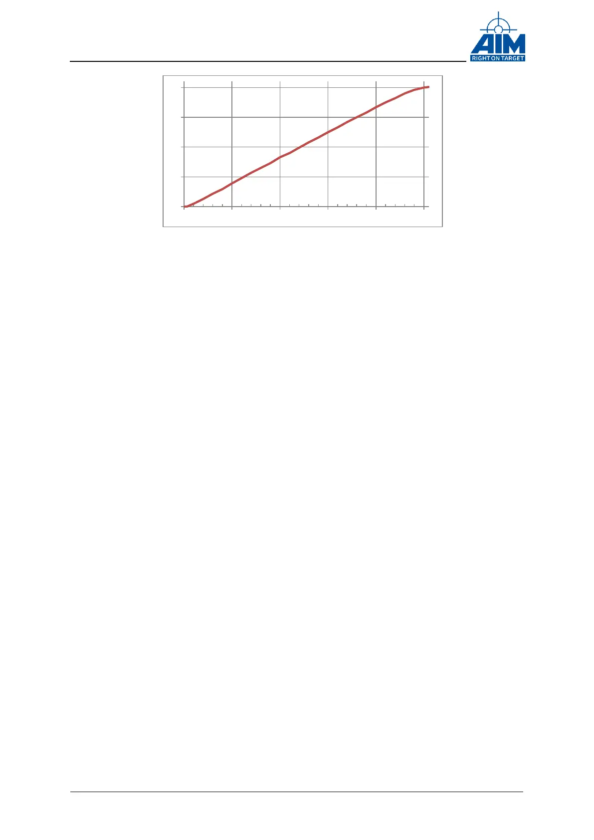
The X-Axis (→) is the setting of the programmed amplitude values (0…255), whereas
the Y-Axis (↑) is the output amplitude [VPP] on the Transformer coupled Stub
(0…20VPP). This diagram shows a characteristic behaviour of the output amplitude, but
exact settings might be slightly different.
0
5
10
15
20
0 50 100 150 200 250
Figure 4-3 Diagram MILbus output amplitude versus amplitude settings