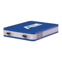
ANET3910-EN User’s Manual
Single implementation with bus switching logic (not redundant)
Full error detection and indication
Transmitter Initialize Time measurement with 250ns resolution
Gap/ Response Time Measurement: For relative response and
inter message gap measurement (<=100µs) an internal timer is
used with 250 ns resolution.
The physical I/O Interface with one dual redundant
MIL-STD-1553/STANAG3838 stream. It consists of the MIL-STD-
1553B/STANAG3838 transceiver and a respective transformer.
Programmable Output Voltage (separate for primary and secondary
bus): appr. 0 to 20 Volts (peak to peak) transformer coupled into 70
Ohm.
Bus coupling modes:
- Transformer coupled
- Direct coupled
- Network coupled (Transformer coupled with on-board
resistor network emulation)
- Isolated
Characteristic Input-Impedance: 50
TX-Output Voltage: 6.0V ... 9.0V
RX-Input Voltage: 0.15V ... 2.0V
For absolute time tagging, a special time code processor
implements an IRIG-B-122 encoder/decoder. If no external IRIG
source is available a time code in IRIG-B-122 format is generated
and can be used to synchronize multiple boards or modules.
Signal Waveform: Amplitude modulated sine wave
or square wave signal
Modulation Ratio: 3:1 to 6:1
Input Amplitude: 0.6V
p-p
to 5V
p-p
Input Impedance: ~ 10k ohm
Time Jitter: +/- 5µs (depending on the input signal quality)
Freewheeling accuracy after 10 Minutes < 1ppm (assuming input
signal accuracy better than 50ppm)
Absolute Accuracy: +/-25ppm (standard Oscillator)

 Loading...