118
REPLACEMENT OF MAIN COMPONENTS
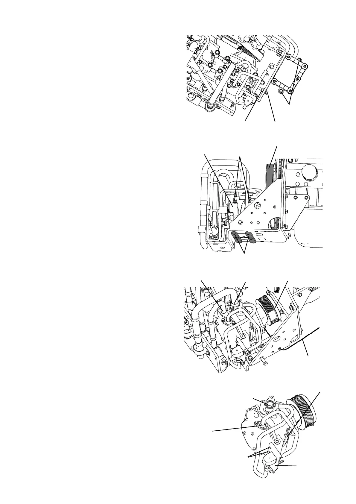
7) Unscrew 2 bolts and move the exhaust water drain
filter not to cause an obstrustion.
8) Loosen a locknut and an adjustment bolt adequate-
ly.
9) Take out 4 bolts.
NOTE) When removing the mounting bolts, catch the
2 stays (plate-shaped) with your hand so that
they do not fall on the bottom plate.
10) Move No. 1 compressor inward, and remove the
compressor belt.
3. Check that no refrigerant is left in the main unit, and
perform the following work.
1) Turn the compressor pulley (clutch plate as for No.
2 compressor) a few turns by hand.
2) Loosen each 2 bolts of intake (upper side) and
discharge ports.
3) Disconnect the oil tube from the compressor unit.
4) Dismount the compressor from the bracket.
NOTE) Take care not to damage the flanges (contact
surfaces of the o-rings) of the intake and
discharge ports.
4. Place the removed compressor on the table approx-
imately 4 inch (100 mm) high, and perform the
following work.
1) Unscrew each 2 bolts of compressor capacity elec-
tromagnetic valve port and intake port.
2) Unscrew 2 bolts to remove the electromagnetic
compressor capacity valve with the stay.
3) Remove the compressor heater from the compres-
sor.
Bolts
Lock nut
Adjustment bolt
Stays
Compressor belt
Bolts
No. 1
(4 pieces)
Intake port
Discharge port
Oil tube
Pulley
Compressor heater
Stay
Bolts
Compressor capacity
electromagnetic valve
port
Intake port
 Loading...