22
Introduction
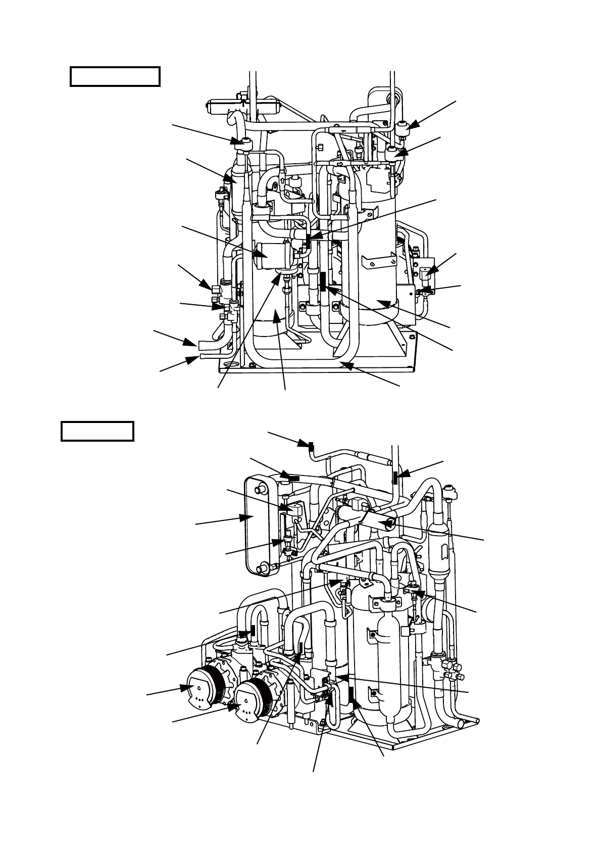
Figure 2 Refrigerant system
SIDE PANEL SIDE
Sub heat exchanger
liquid flow control valve
Outdoor heat exchanger
liquid flow control valve
Strainer (for vapor)
Subcooling valve
Dryer filter
Stop valve (for vapor)
Stop valve (for liquid)
Refrigerant line connection
port (for vapor)
Accumulator
Accumulator outlet
temperature sensor
Outdoor liquid pipe
temperature sensor
Refrigerant line connection
port (for liquid)
Oil separator
Subcooling heat exchanger (double pipe)
Electromagnetic
compressor capacity
valve 1
Refrigerant high
pressure switch 1
Strainer (for liquid)
ENGINE SIDE
Outdoor heat exchanger liquid temperature sensor
Outdoor heat exchanger vapor
temperature sensor
Sub heat exchanger liquid temperature sensor
Hot gas bypass valve
Sub heat exchanger
Refrigerant low pressure sensor
Oil bypass control valve
Reversing valve
Refrigerant high
pressure sensor 1
Compressor discharge pipe
temperature sensor 1
Compressor intake temperature sensor
Compressor 1
Compressor 2
(with clutch)
Compressor discharge pipe temperature sensor 2
Electromagnetic compressor capacity valve 2
Refrigerant high
pressure switch 2
 Loading...