www.aja.com
123
FS4 Frame Synchronizer/Converter v1.1
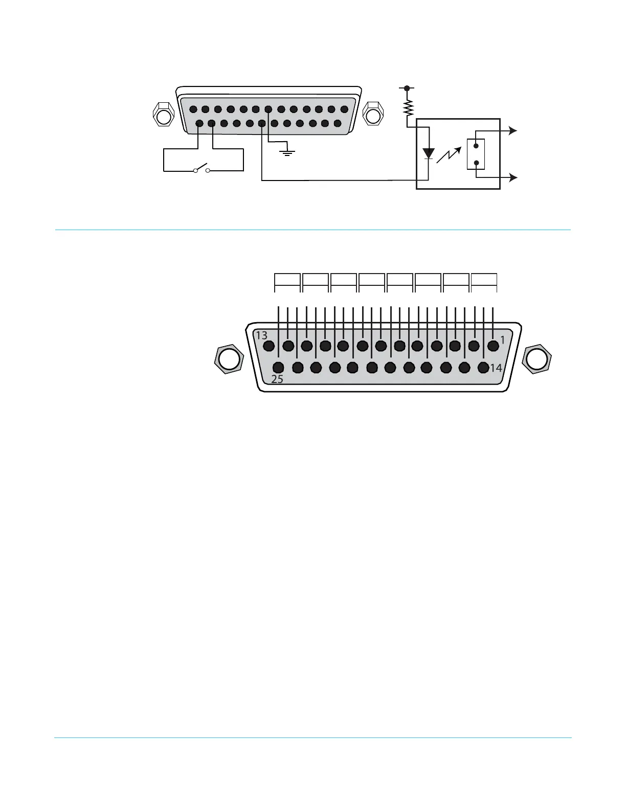
Figure 39. Typical GPI Input and Output Connections
Audio Connection Pinouts
Digital Audio Figure 40. Digital Audio Connector Pinout
The pinout scheme above is used for the AES/EBU digital audio connections. Each
channel handles a pair of digital audio signals (16 total per connector). The top connector
is for digital audio input channels 1-16, and the bottom connector is for digital audio
output channels 1-16.
1
14202425
13
7
GPI Out 4
xmit+
xmit-
Optical Relay (SSR)
To Tally Lamp etc.
GPI GND 4
GPI
GND 1
GPI
In 1
+V
GGG
15/1613/14
G
5/6
G
1/2
G
9/10 11/12
G
7/8
G
3/4
AES
Channels
G = Ground
To MUX into unbalanced AES BNC connections, use Balun 75 ohm adapter.
110 Ohm Balanced
- + - + - + - + - + - + - + - +