www.aja.com
44
FS4 Frame Synchronizer/Converter v1.1
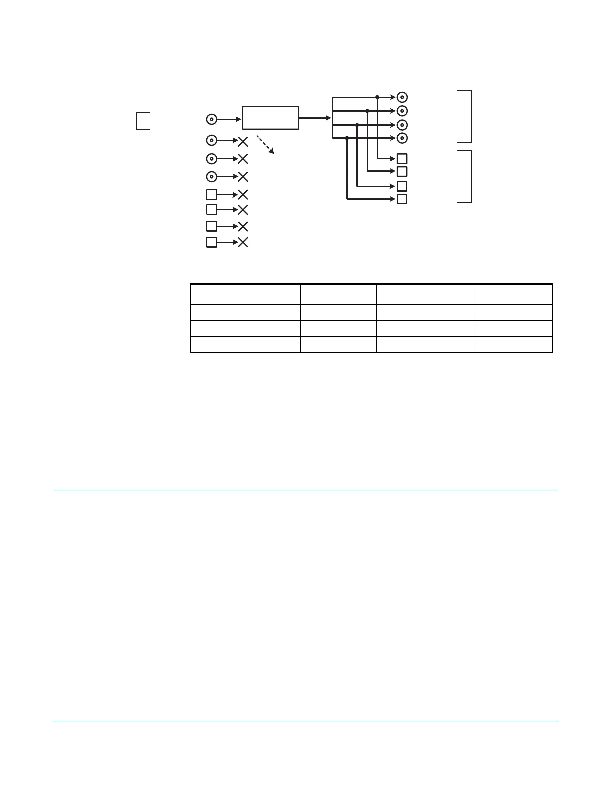
Figure 27. Single Channel Mode, Up Conversion
GPI Connections The FS4 has four GPI inputs and four GPI outputs. The GPI inputs and outputs are
electrically isolated from the power and ground on the FS4 frame. Electrical isolation is
provided for up to four pieces of external equipment.
See “GPI Pinouts” on page 122 for information on how to wire the GPI connector to work
with external devices that you want to use to control the FS4 or that you want the FS4 to
control.
Stand Alone Tests
The stand alone tests can be performed without a computer, using the FS4 front panel
controls and rear connections. The following procedures assume the FS4 is at factory
defaults (taken from a newly opened box). If not set to defaults, the FS4 may behave
differently.
NOTE: FS4 units are configured at the factory to operate in Four Channel Mode.
First Power Up The following workflow powers up a default FS4 and demonstrates some example
alarms.
Setup • Ensure the FS4 is completely disconnected (all video, audio, network, and power
connector ports are empty).
Procedure 1. Connect both FS4 power cords to mains AC and allow time for the unit to boot up.
Observe the front panel LEDs.
SDI Out 7 SFP
SDI Out 8 SFP
SDI Out 5 SFP
(w Embedded Audio)
SDI Out 6 SFP
SDI Out 4 BNC
SDI Out 1 BNC
(w Embedded Audio)
SDI Out 2 BNC
SDI Out 3 BNC
4K/UHD
Video Processor
SDI In 1 BNC
(w Embedded Audio)
SDI In 2 BNC
SDI In 3 BNC
SDI In 4 BNC
SDI In 5 SFP
SDI In 6 SFP
SDI In 7 SFP
SDI In 8 SFP
Signal Z
1.5G HD 1080i
Signal Z
Up Convert to
Quad Link UHD
Signal Z
Up Convert to
Quad Link UHD
Two copies of the
same signal on the
BNC and SFP outputs
Frame Sync Up Conversion
Single Channel Mode
Up to 16 channels of
embedded audio is
disembedded and sent
to Audio Processor
Table 8. FS4 Menu Settings for Figure 26
Channel Select Button Video Button Menu Name Setting
VID1 INPUT 1 Input SDI1
VID1 FORMAT 1 Output Format UHD2160p5994
VID1 FORMAT 2.0 Link Cfg SDI1 QuadLink LvlA