186 Rockwell Automation Publication 290E-UM001B-EN-P - June 2012
Appendix A Applying More Than One ArmorStart LT Motor Controller in a Single Branch Circuit on Industrial Machinery
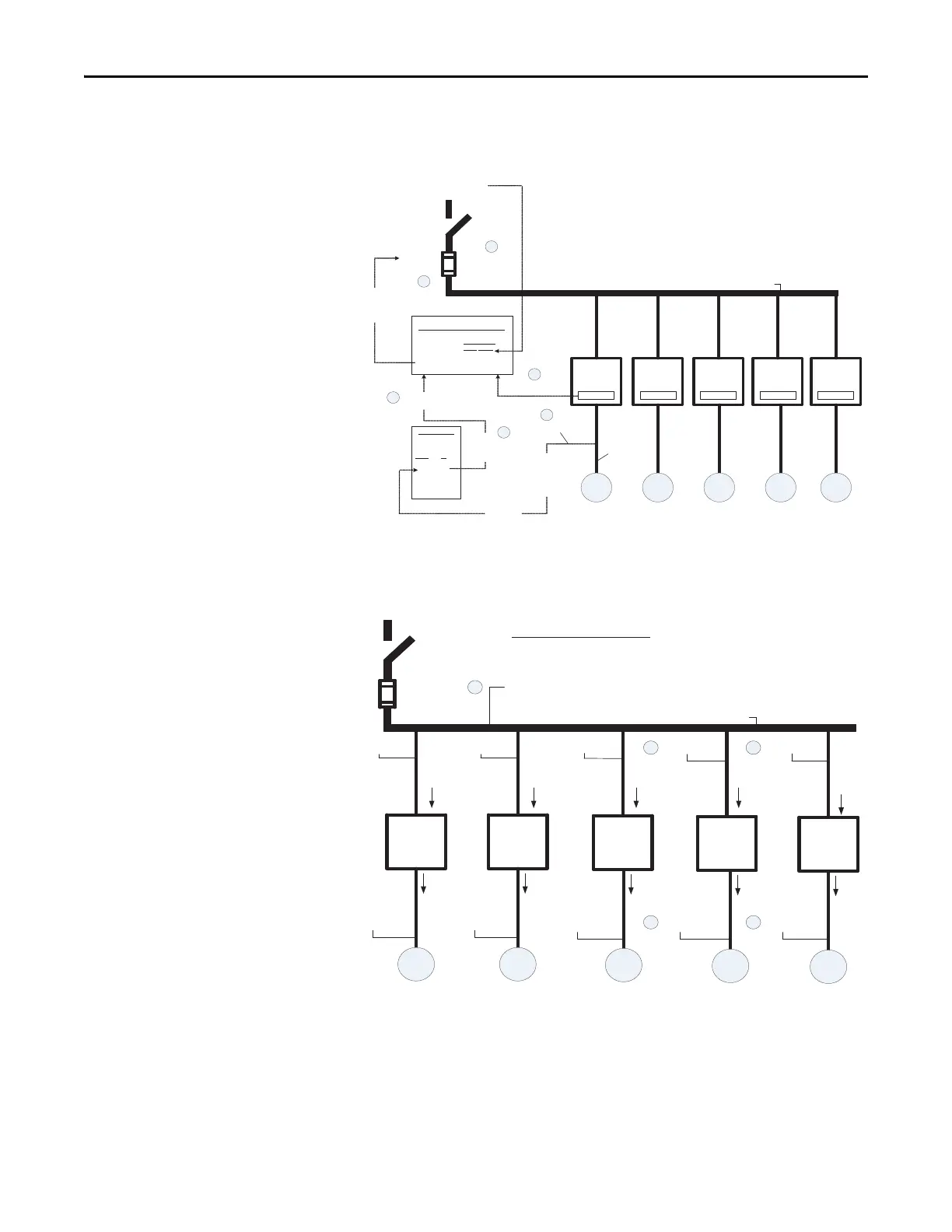
Figure 61 - ArmorStart LT NFPA 79 Multi-Motor Branch Circuit —
Conductor and Controller Protection
Figure 62 - ArmorStart LT NFPA 79 Multi-Motor Branch Circuit Minimum Conductor Ampacity
½ HP
Bulletin 294
2 HP
Bulletin 294
5 HP
Bulletin 291
5 HP
Bulletin 290
1 HP
Bulletin 294
Overload
Class 10
Overload
Class 10
Overload
Class 10/15/20
Overload
Class 10/15/20
Overload
Class 10
Nameplate* Nameplate* Nameplate* Nameplate* Nameplate*
1/2 HP
FLC =
1.1 A**
2 HP
FLC =
3.4 A**
5 HP
FLC =
7.6 A**
5 HP
FLC =
7.6 A**
1 HP
FLC =
2.1 A**
14 AWG14 AWG
14 AWG14 AWG
14 AWG14 AWG
14 AWG14 AWG
14 AWG14 AWG
Combined Load Conductors
10 AWG
* Each controller is suitable for group installation with the same maximum ratings of fuse.
** Table 430.250 of NFPA 70-2011
Electrical Supply -
480Y/277V
Available Fault Current
Sym. Amps RMS 9 KA
Disconnecting
Means
Branch short-circuit
and ground-fault
protection device
Fuses
45 A Max,
CC, J or T
Controller
ratings
further
restrict the
fuse
Compare to
controller max
fuse ratings
“Suitable for Motor Group Installation”
Max. Ratings
5 KA 10 KA
45A 45A*
Sym. Amps RMS
Fuse
* Type CC, J and T fuses only
Conductor
protection -
60 A max,
any class
Determine
fuse class
and max
rating for
conductor
protection
Conductor
protection
“Smallest
conductor”
7.2.10.4(2) -
“smallest
conductor in
the circuit”
= 14 AWG
Table 7.2.10.4
Max
Fuse
AWG (A)
- -
14 60
12 80
10 100
8 150
- -
a
d
d
a
b
c
Electrical Supply
Min Amp. =
125% * 1.8 A
Min Amp. =
125% * 5.5 A
Min Amp. =
125% * 7.6 A
Min Amp. =
125% * 7.6 A
Min Amp. =
125% * 3.0 A
Min Amp. =
125% * 1.1A
Min Amp. =
125% * 3.4 A
Min Amp. =
125% * 7.6 A
Min Amp. =
125% * 7.6 A
Min Amp. =
125% * 2.1 A
Minimum Required Ampacity (MRA)
MRA = 1.25 * Max {controller input currents} + Sum {remaining controller input currents}
Controller input currents = {I1,I2,I3,I4,I5}
Max controller input current = I3 = I4, choose I3 as Max (either is ok)
MRA = 1.25 * I3 + (I1 + I2 + I4 + I5}
= 1.25 * 7.6 A + (1.8 A + 5.5 A + 7.6 A + 3.0 A) = 27.4 A
c
a
b
a
b
½ HP
Bulletin
294
2 HP
Bulletin
294
5 HP
Bulletin
291
5 HP
Bulletin
290
1 HP
Bulletin
294
Combined Load Conductors
I1 =
1.8 A
I2 =
5.5 A
I3 =
7.6 A
I4 =
7.6 A
I5 =
3.0 A
1/2 HP
FLC =
1.1 A**
2 HP
FLC =
3.4 A**
5 HP
FLC =
7.6 A**
5 HP
FLC =
7.6 A**
1 HP
FLC =
2.1 A**
** Table 430.250 of NFPA 70-2011
1.1 A 3.4 A 7.6 A 7.6 A 2.1 A
14 AWG14 AWG
14 AWG14 AWG
14 AWG14 AWG
14 AWG14 AWG
14 AWG14 AWG
10 AWG
 Loading...