64 Rockwell Automation Publication 290E-UM001B-EN-P - June 2012
Chapter 2 Installation and Wiring
ArmorConnect Power
Media Receptacles
ArmorStart LT utilizes a M22 male receptacle for power inputs and a M22
female receptacle for motor or motor brake output.
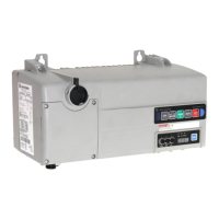
Motor Connector (optional)
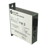
Source Brake Connector (optional)
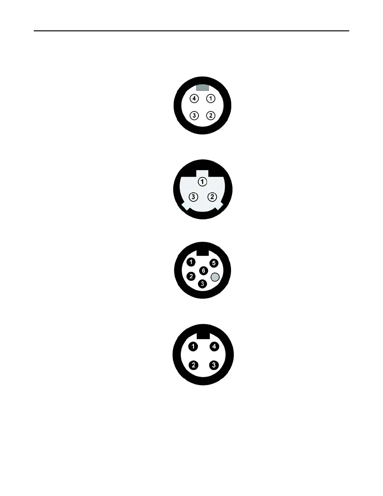
Incoming Control Power (optional) – 24V DC Only
Incoming Three-Phase Power (optional)
Pin 1 - T1 (black)
Pin 2 - T2 (white)
Pin 3 - T3 (red)
Pin 4 - Ground (green/yellow)
Pin 1 - Ground (green/yellow)
Pin 2 - B1(black)
Pin 3 -B2 (white)
Pin 1 – (+V) Unswitched (A3/red)
Pin 2 – (–V) Common (A2/black)
Pin 3 – Not used (green)
Pin 4 – Not used (blank)
Pin 5 – (+V) Switched (A1/blue)
Pin 6 – Not used (white)
Pin 1 - L1 (black)
Pin 2 - L2 (white)
Pin 3 - L3 (red)
Pin 4 - Ground (green/yellow)
 Loading...