Rockwell Automation Publication 290E-UM001B-EN-P - June 2012 43
Installation and Wiring Chapter 2
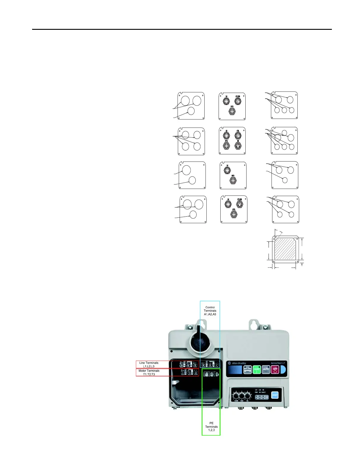
Dimensions are shown in millimeters (inches). Dimensions are not intended
to be used for manufacturing purposes. All dimensions are subject to change.
Figure 18 - ArmorStart LT Gland Plate Matrix
Connection Locations
Figure 19 - Internal Power, Control, and Ground Locations
1.00 in.
(25.4 mm)
1.00 in.
(25.4 mm)
1.00 in.
(25.4 mm)
0.75 in.
(19.05 mm)
0.75 in.
(19.05 mm)
0.75 in.
(19.05 mm)
0.75 in.
(19.05 mm)
Dia. 25.5 mm
Dia. 25.5 mm
Dia. 25.5 mm
Dia. 20.5 mm
Dia. 20.5 mm
G1 Conduit G2 Media
Standard
U.S. Trade Knock-outs
G3 Conduit
Daisy Chaining
IP66 Metric Fittings
No Internal Power Supply
No Source Brake
Source Brake
No Internal Power Supply
Internal Power Supply
No Source Brake
Internal Power Supply
and Source Brake
User Modied
Dia. 25.5 mm
Dia. 20.5 mm
Dia. 20.5 mm
Cat. No.
290-G3-A2
290-G3-A3
290-G3-A4
290-G3-A5
290-G3-A1
45°
66.1 mm
11.8 mm
10.1 mm
91.3 mm
80.7 mm
Gland Plate Clearances
Modications are not permitted in the keepout region. Fitting(s) should be oriented
so that they do not interfere with the enclosure when the gland plate is installed.
Torque the gland mounting screws to 12…14 in•lb (1.3…1.6 N•m).
 Loading...