Rockwell Automation Publication 290E-UM001B-EN-P - June 2012 45
Installation and Wiring Chapter 2
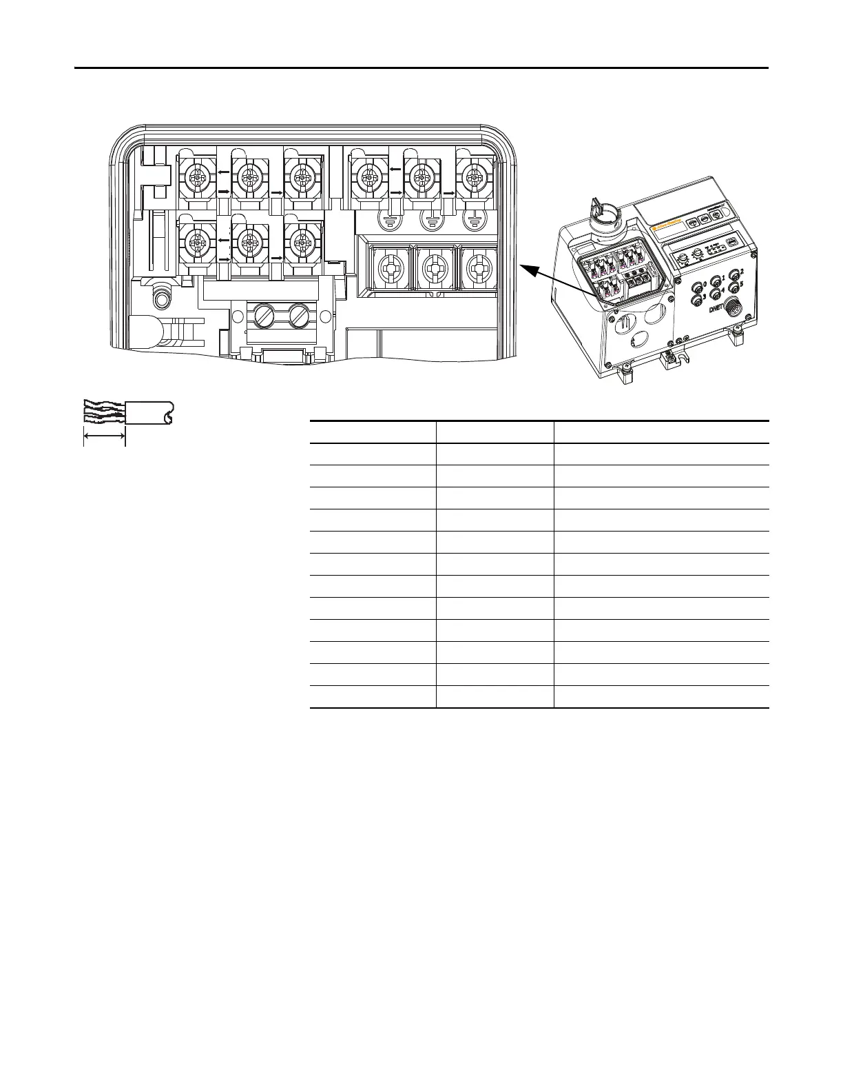
Figure 21 - ArmorStart LT Power and Control Terminals
➊ When internal power supply option is selected, no connection is made here.
➋ Available only with Bulletin 294E.
L2
L1
T1
L3
T2
T3
A2
A3
A1
PE
B1 B2
Wire Strip Length
0.35 ± 0.01 in.
(9 ± 0.2 mm)
Table 7 - Power, Control, and Ground Terminal Designations
Terminal Designations Wires/Connections Description
A1 2 Switched 24V DC Control Power (+) ➊
A2 2 Control Power Common (–) ➊
A3 2 Unswitched 24V DC Control Power (+) ➊
PE 2 Ground
L1 2 Line Power – Phase A
L2 2 Line Power – Phase B
L3 2 Line Power – Phase C
T1 1 Motor Connection – Phase A
T2 1 Motor Connection – Phase B
T3 1 Motor Connection – Phase C
B1 1 Source Brake Connection – B1 ➋
B2 1 Source Brake Connection – B2 ➋
 Loading...