Rockwell Automation Publication 5069-UM004A-EN-P - April 2019 23
Digital Module Operation in a Control System Chapter 1
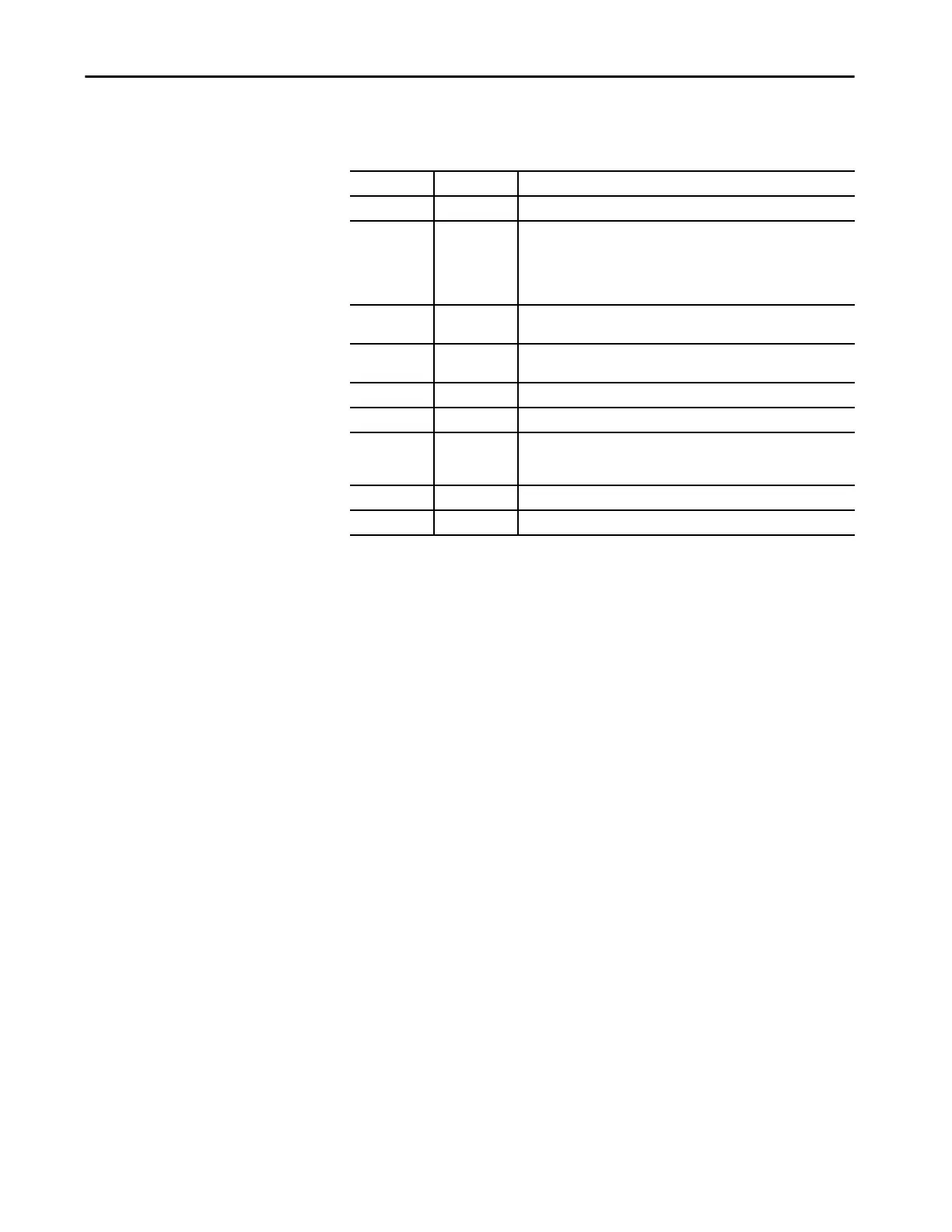
Table 5 - Compact 5000 I/O Digital Module Parts
Item Item Description
1 DIN rail latch Locks the module on the DIN rail.
2 Module and
power status
indicators
Standard modules:
• STATUS - Displays the status of communication and module health.
Safety modules:
• MOD Status - Displays the status of communication and module health.
• SA - Displays whether SA power is applied to the module.
3 I/O status
indicators
Displays the status of the input/output point.
4 Interlocking
pieces
Securely installs Compact 5000 I/O digital modules in the system.
5 RTB handle Anchors the RTB on the module.
6 RTB Provides a wiring interface for the module.
7 MOD Power bus
and SA Power
bus connectors
Pass system-side and field-side power across the internal circuitry of the
module in a Compact 5000 I/O system. The connectors are isolated from
each other.
8 RTB lower tab Hooks RTB onto the module to begin installation.
9 Lower hook Used with cable tie after you wire the module.

 Loading...

