102 Rockwell Automation Publication 2094-UM001J-EN-P - March 2017
Chapter 5 Connect the Kinetix 6000 Drive System
This example applies to a common-bus follower IAM module.
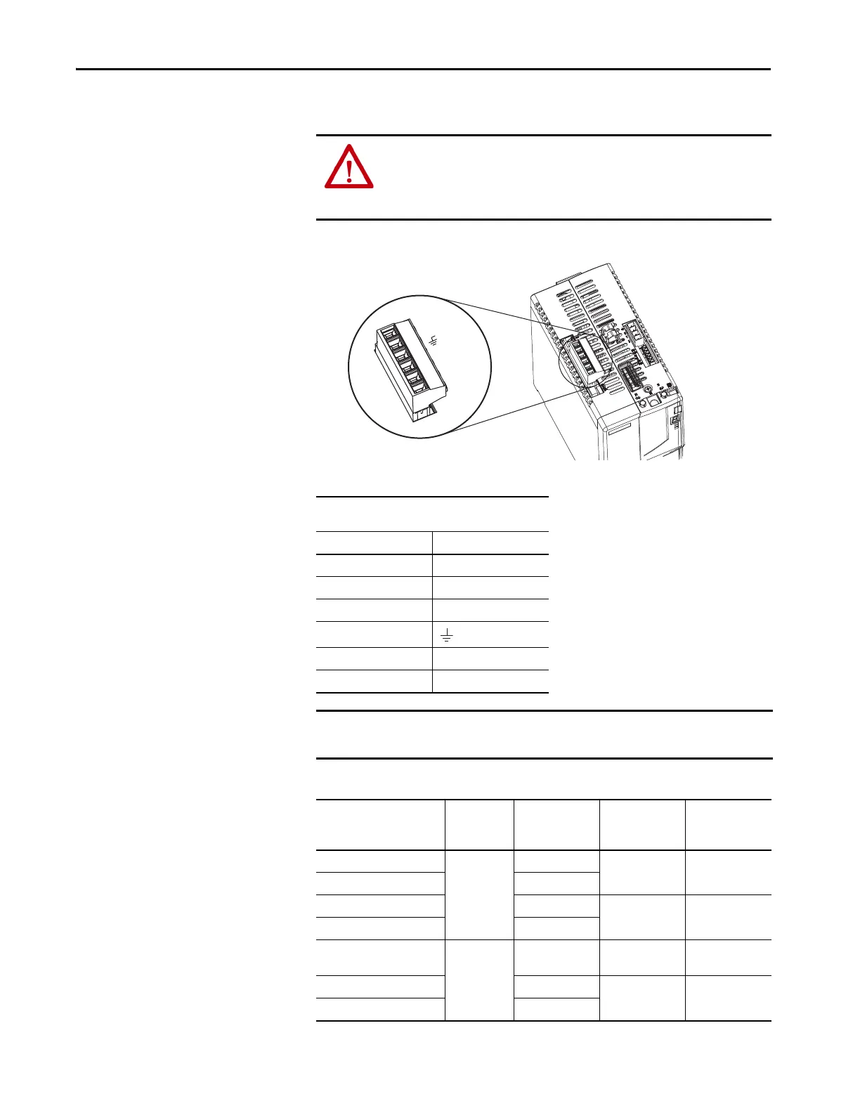
Figure 51 - IAM Module (IPD connector)
Table 66 - Input Power (IPD) Connections
Table 67 - Termination Specifications
ATTENTION: Make sure the common-bus power connections are correct
when wiring the IPD connector plug and that the plug is fully engaged in the
module connector. Incorrect wiring/polarity or loose wiring can cause
explosion or damage to equipment.
Kinetix 6000
IAM Module, Top View
IPD Connector
(IAM or follower IAM module)
IPD Pin Signal
6N.C.
5N.C.
4N.C.
3
2DC+
1DC-
IMPORTANT Do not connect three-phase input power to the common-bus follower IAM
module.
IAM Module Cat. No. Input VAC
Recommended
Wire Size
mm
2
(AWG)
Strip Length
mm (in.)
Torque Value
N•m (lb•in)
2094-AC05-Mxx-x
230V AC
2.5 (14)
10 (0.38)
0.5…0.6
(4.4…5.3)
2094-AC09-M02-x 4.0 (12)
2094-AC16-M03-x 10 (8)
16 (0.63)
2.4…3.0
(21.6…26.5)
2094-AC32-M05-x 30 (3)
2094-BC01-Mxx-x
2094-BC02-M02-x
460V AC
2.5 (14) 10 (0.38)
1.2…1.5
(10.6…13.2)
2094-BC04-M03-x 6 (10)
16 (0.63)
2.4…3.0
(21.6…26.5)
2094-BC07-M05-x 30 (3)
 Loading...


