EasyManuals Logo

Allen-Bradley Kinetix 6000 User Manual

Allen-Bradley Kinetix 6000
290 pages
To Next Page IconTo Next Page
To Previous Page IconTo Previous Page
Page #55 background imageLoading...
Page #55 background image
Rockwell Automation Publication 2094-UM001J-EN-P - March 2017 55
Mount the Kinetix 6000 Drive System Chapter 3
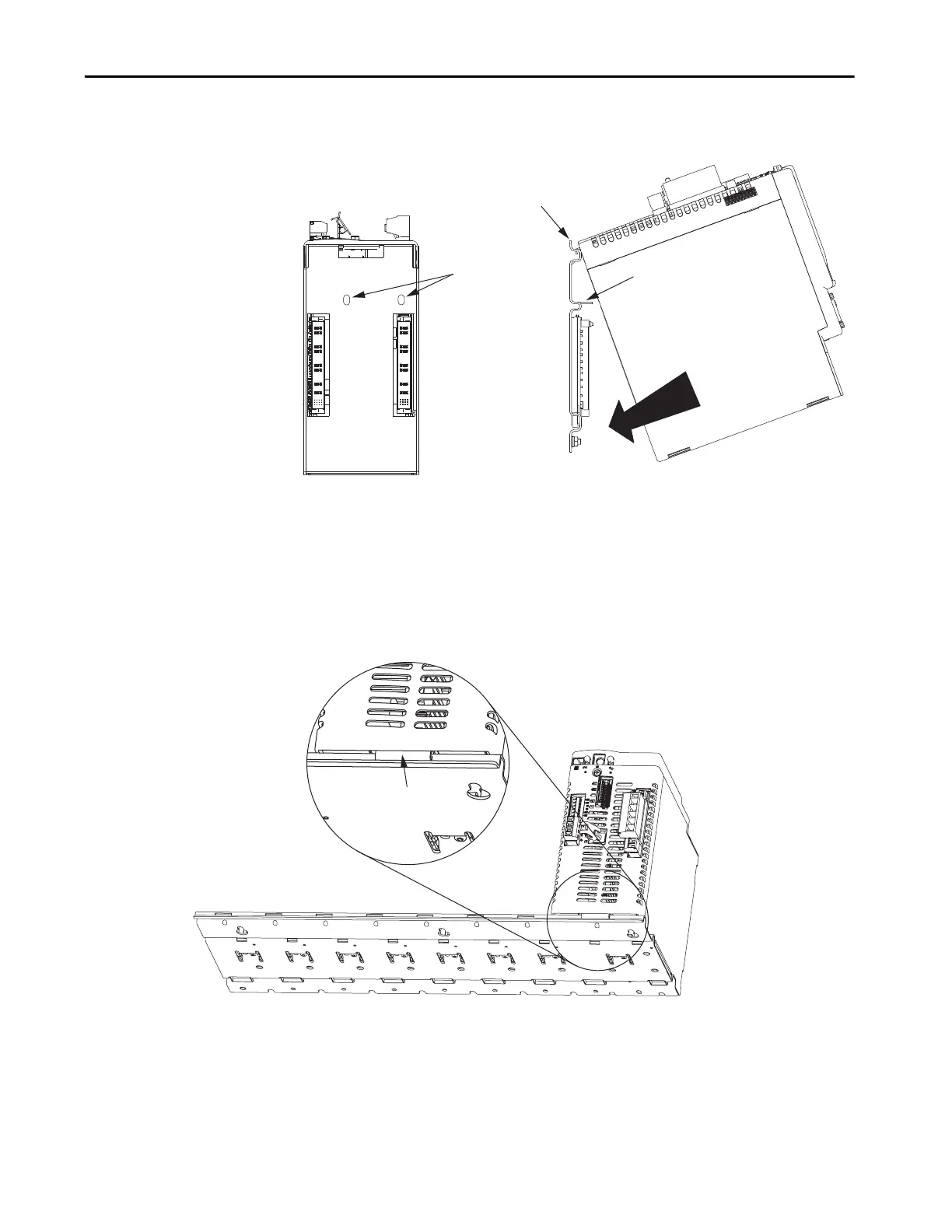
4. Pivot module downward and align the guide pins on the power rail with
the guide pin holes in the back of the module.
5. Gently push the module against the power rail connectors and into the
final mounting position.
Guide Pin
Holes
Power rail (side view)
in upright vertical position.
Guide Pins
Pivot module downward
and align with guide pins.
Kinetix 6000 IAM, AM, IPIM, Shunt,
or Slot-filler Module, Side View
(IAM module is shown)
Kinetix 6000 IAM, AM, IPIM, Shunt,
or Slot-filler Module, Rear View
(IAM module is shown)
TIP The IAM module can have two or three power rail connectors and guide
pins, the AM module can have one or two, all other modules have one.
Power Rail
Bracket secured in slot.
Kinetix 6000 IAM, AM, IPIM,
Shunt, or Slot-filler Module
(IAM module is shown)

Table of Contents

Other manuals for Allen-Bradley Kinetix 6000

Questions and Answers:

Question and Answer IconNeed help?

Do you have a question about the Allen-Bradley Kinetix 6000 and is the answer not in the manual?

Allen-Bradley Kinetix 6000 Specifications

General IconGeneral
Control TypeDigital
FeedbackResolver, Encoder
Protection RatingIP20
Power Range0.4…22 kW
CommunicationEthernet/IP
Ambient Temperature0°C to 50°C
AxisSingle-axis, Multi-axis
SafetySafe Torque-Off
Control ModesVelocity, Torque, Position
Relative Humidity5% to 95% (non-condensing)
Vibration Resistance5.9 m/s² (0.6 g) from 10 Hz to 500 Hz
Shock Resistance15 g, 11 ms
Storage Temperature-40°C to 70°C

Related product manuals