Rockwell Automation Publication 2094-UM001J-EN-P - March 2017 91
Connect the Kinetix 6000 Drive System Chapter 5
3. Swing the front panel open to the right, as shown, and locate the ground
jumper.
4. Move the ground jumper.
5. Replace the IAM module front panel and two screws.
Apply 1.6 N•m (14 lb•in) torque.
6. Mount the IAM module back on the power rail.
For detailed instructions, refer to Replace Kinetix 6000 Drive Modules
on page 183
.
IMPORTANT Do not attempt to remove the front panel from the IAM module. The
front panel status indicators and switches are also connected to the
IAM module with a ribbon cable. The ribbon cable acts like a hinge
and lets you swing the front panel open to access the ground
jumper.
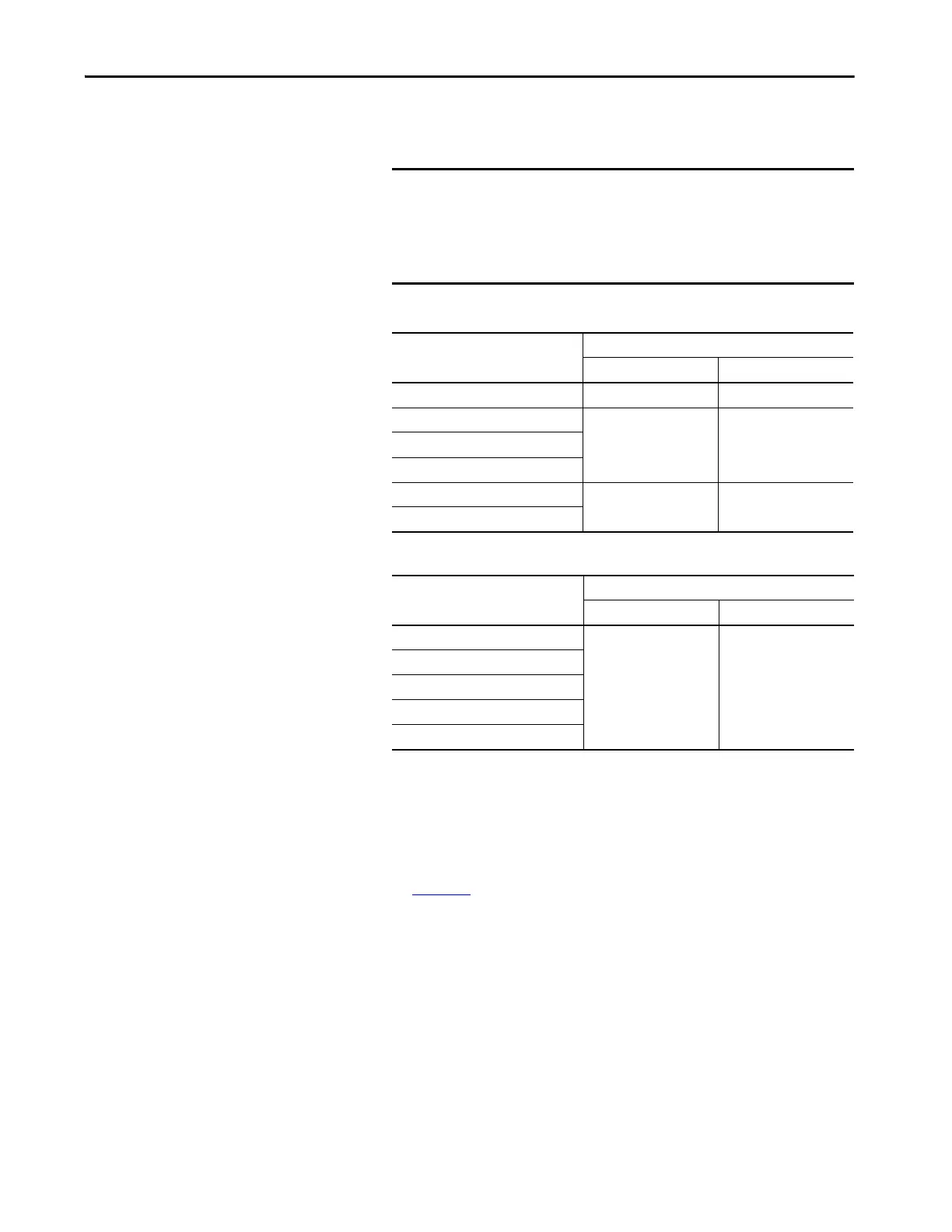
IAM Module (series A)
Configuration
Grounded (default) Ungrounded
2094-ACxx-Mxx-x (230V)
(1)
(1) Applies to series A and C (230V) drives.
P15 and P16 P15 and P17
2094-BC01-MP5-x (460V)
P13 and P14 P13 and P122094-BC01-M01-x (460V)
2094-BC02-M02-x (460V)
2094-BC04-M03-x (460V)
P14 and P13 P14 and P12
2094-BC07-M05-x (460V)
IAM Module (series B and C)
Configuration
Grounded (default) Ungrounded
2094-BC01-MP5-S (460V)
P16 and P17 P18 and P19
2094-BC01-M01-S (460V)
2094-BC02-M02-S (460V)
2094-BC04-M03-S (460V)
2094-BC07-M05-S (460V)
 Loading...


