348 Rockwell Automation Publication 1756-RM003N-EN-P - October 2011
Chapter 8 Array (File)/Misc. Instructions (FAL, FSC, COP, CPS, FLL, AVE, SRT, STD, SIZE)
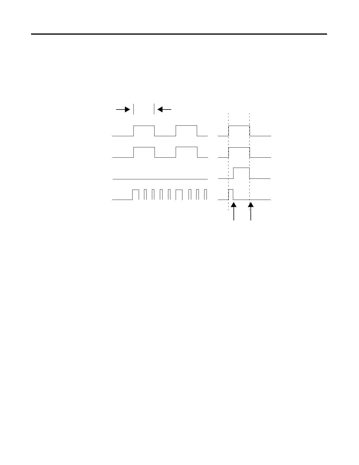
The following timing diagram shows the relationship between status bits and
instruction operation. Execution occurs only in a scan in which the rung-
condition-in goes from false to true. Each time this occurs, only one element of
the array is manipulated. If the rung-condition-in remains true for more than one
scan, the instruction only executes during the first scan.
The .EN bit is set when rung-condition-in is true. The .DN bit is set when the
last element in the array has been manipulated. When the last element has been
manipulated and the rung-condition-in goes false, the .EN bit, the .DN bit, and
the .POS value are cleared.
The difference between incremental mode and numerical mode at a rate of one
element per scan is as follows:
· Numerical mode with any number of elements per scan requires only one
false-to-true transition of the rung-condition-in to start execution. The
instruction continues to execute the specified number of elements each
scan until completion regardless of the state of the rung-condition-in.
· Incremental mode requires the rung-condition-in to change from false to
true to manipulate one element in the array.
One
Scan
Rung-condition-in
.EN Bit
.DN Bit
Scan Of The Instruction
Operation Complete Clears Status Bits And clears .POS
Value
40014

 Loading...

