526 Rockwell Automation Publication 1756-RM003N-EN-P - October 2011
Chapter 13 Special Instructions (FBC, DDT, DTR, PID)
Instructions for setting a bumpless restart.
Derivative Smoothing
The derivative calculation is enhanced by a derivative smoothing filter. This
first order, low pass, digital filter helps to minimize large derivative term spikes
caused by noise in the PV. This smoothing becomes more aggressive with
larger values of derivative gain. You can disable derivative smoothing if your
process requires very large values of derivative gain (K
d
> 10, for example). To
disable derivative smoothing, select the “No derivative smoothing” option on
the Configuration tab or set the .NDF bit in the PID structure.
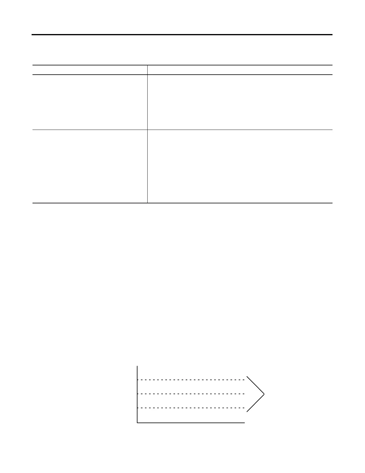
Set the Deadband
The adjustable deadband lets you select an error range above and below the
setpoint where output does not change as long as the error remains within this
range. This deadband lets you control how closely the process variable matches
the setpoint without changing the output. The deadband also helps to
minimize wear and tear on your final control device.
Do this Details
Configure the 1756 analog output module’s channel that
receives the control variable from the PID instruction
Select the “hold for initialization” checkbox on the properties page for the specific channel of
the module.
This tells the analog output module that when the controller returns to Run mode or re-
establishes communications with the module, the module should hold the analog output at its
current value until the value sent from the controller matches (within 0.1% of span) the
current value used by the output channel. The controller’s output will ramp to the currently
held output value by making use of the .BIAS term. This ramping is similar to auto
bumpless transfer.
Enter the Inhold bit tag and Inhold Value tag in the
PID instruction
The 1756 analog output module returns two values for each channel in its input data
structure. The InHold status bit (.Ch2InHold, for example), when true, indicates that the
analog output channel is holding its value. The Data readback value (.Ch2Data, for example)
shows the current output value in engineering units.
Enter the tag of the InHold status bit as the InHold bit parameter of the PID instruction. Enter
the tag of the Data readback value as the Inhold Value parameter.
When he Inhold bit goes true, the PID instruction moves the Inhold Value into the Control
variable output and re-initializes to support a bumpless restart at that value. When the analog
output module receives this value back from the controller, it turns off the InHold status bit,
which allows the PID instruction to start controlling normally.
Error Within Deadband Range
+ Deadband
Setpoint
- Deadband
Time
41026

 Loading...


