Rockwell Automation Publication 1756-RM003N-EN-P - October 2011 659
Function Block Attributes Appendix B
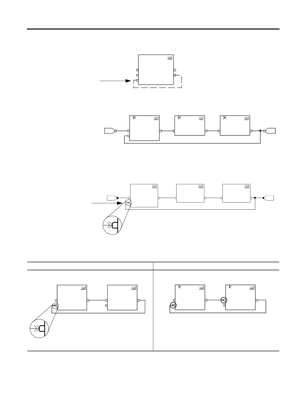
If a group of blocks are in a loop, the controller cannot determine which block to
execute first. In other words, it cannot resolve the loop.
To identify which block to execute first, mark the input wire that creates the loop
(the feedback wire) with the Assume Data Available indicator. In the following
example, block 1 uses the output from block 3 that was produced in the previous
execution of the routine.
The Assume Data Available indicator defines the data flow within the loop. The
arrow indicates that the data serves as input to the first block in the loop.
Do not mark all the wires of a loop with the Assume Data Available indicator.
This input pin uses an output that the
block produced on the previous scan.
12 3
This input pin uses the output that
block 3 produced on the previous
scan.
Assume Data Available indicator
This is okay This is NOT okay
The Assume Data Available indicator defines the data flow within the loop.
The controller cannot resolve the loop because all the wires use the
Assume Data Available indicator.
Assume Data Available
indicator
21

 Loading...

