Rockwell Automation Publication 2080-RM001D-EN-E - February 2015 31
Chapter 3
Ladder Diagram (LD) elements
Ladder diagram elements are the components that you use to build a ladder
diagram program. All the elements listed in the following table can be added to
your ladder diagram from the LD Toolbox within Connected Components
Workbench.
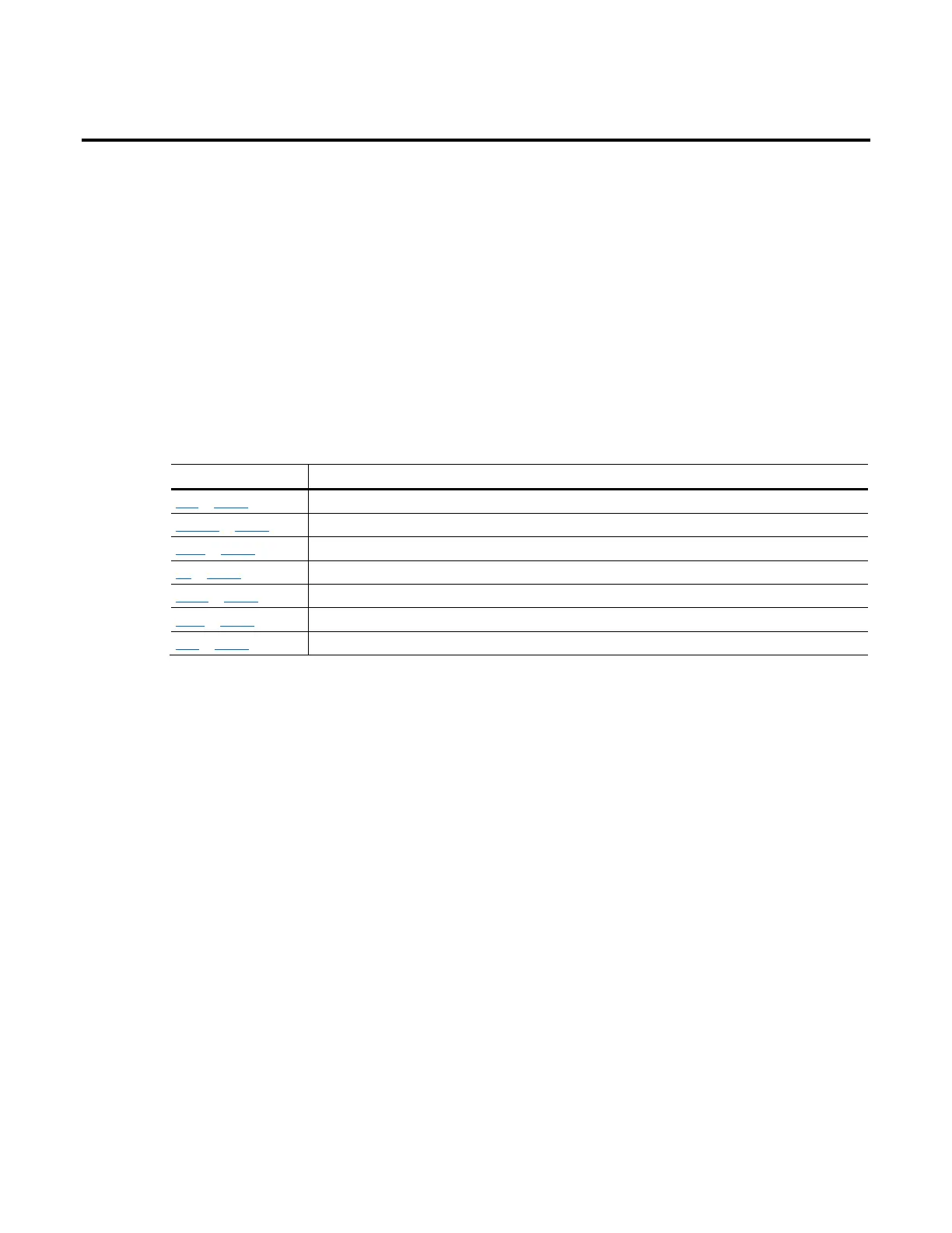
Element Description
Rung on page 31 Represents a group of circuit elements that lead to the activation of a coil.
Block (LD) on page 35 Instructions include operators, functions, and function blocks including user-defined function blocks.
Branch on page 33 Two or more instructions in parallel.
Coil on page 39 Represents the assignment of outputs or internal variables. In an LD program, a coil represents an action.
Contact on page 44 Represents the value or function of an input or internal variable.
Return on page 48 Represents the conditional end of a diagram output.
Jump on page 49 Represents the conditional and unconditional logic in the LD program that control the control the execution of diagrams.
Rung
Rungs are graphic components of an LD diagram that represent a group of circuit
elements that lead to the activation of a coil. Rungs can have labels to identify
them within the diagram. Labels, along with jumps, control the execution of a
diagram. You can enter comments (free-format text) above the rung for
documentation purposes.
Change the default width of rungs
Follow these steps to use a new width for rungs. You cannot adjust the width of
existing rungs within a project.
1. From the Tools menu, select Options.
2. Click IEC Languages, and then Ladder Diagram.
3. Under Container Settings, click Cell Width.
4. Increase the cell width value, and then click OK.

 Loading...


