Settings
122 KE/KX/KG (RIGID) BAH0089-7 02.2020
8.5.1 Wedge ring roller KW / KWM
1. Uncouple the seed drill.
2. Using the tractor hydraulics, lift the soil
tillage implement just enough for the roller
to clear the ground.
3. Support the soil tillage implement against
unintentional lowering.
4. Loosen the bolt.
5. The distance between the scraper (Fig.
124/1) and the roller tube is 10 mm. Adjust
worn scrapers to the correct dimension or
replace.
6. Rotate the roller to check whether the dis-
tance is maintained at all points.
Fig. 124
8.5.2 Tooth packer roller PW
1. Uncouple the seed drill.
2. Using the tractor hydraulics, lift the soil
tillage implement just enough for the roller
to clear the ground.
3. Support the soil tillage implement against
unintentional lowering.
4. Unscrew the screw (Fig. 125/2).
5. Screw on the scraper (Fig. 125/1) with a
distance of 0.5 mm to the roller tube.
6. Rotate the roller to check whether the dis-
tance of 0.5 mm is maintained at all points.
Fig. 125
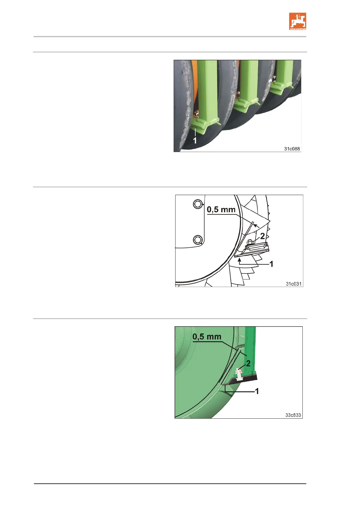
8.5.3 TRW trapeze ring roller
1. Uncouple the seed drill.
2. Using the tractor hydraulics, lift the soil
tillage implement just enough for the roller
to clear the ground.
3. Support the soil tillage implement against
unintentional lowering.
4. Unscrew the screw (Fig. 126/2).
5. Screw on the scraper (Fig. 126/1) with a
distance of 0.5 mm to the roller tube.
6. Rotate the roller to check whether the dis-
tance of 0.5 mm is maintained at all points.
Fig. 126
 Loading...