Settings
KE/KX/KG (RIGID) BAH0089-7 02.2020 125
8.7 Transport locking mechanism for lifting frame (all types)
8.7.1 Locking the lifting frame
1. Instruct any people in the area to stand at a
minimum distance of 10.0 m from the
implement.
2. Pull on the cord (Fig. 132/1).
The locking hook (Fig. 132/2) opens.
3. Actuate the tractor control unit
(green).
The lifting frame is raised. Actuate tractor
control unit
(green) until the lifting frame is
fully raised and locked.
4. Release the (Fig. 132/1) cord.
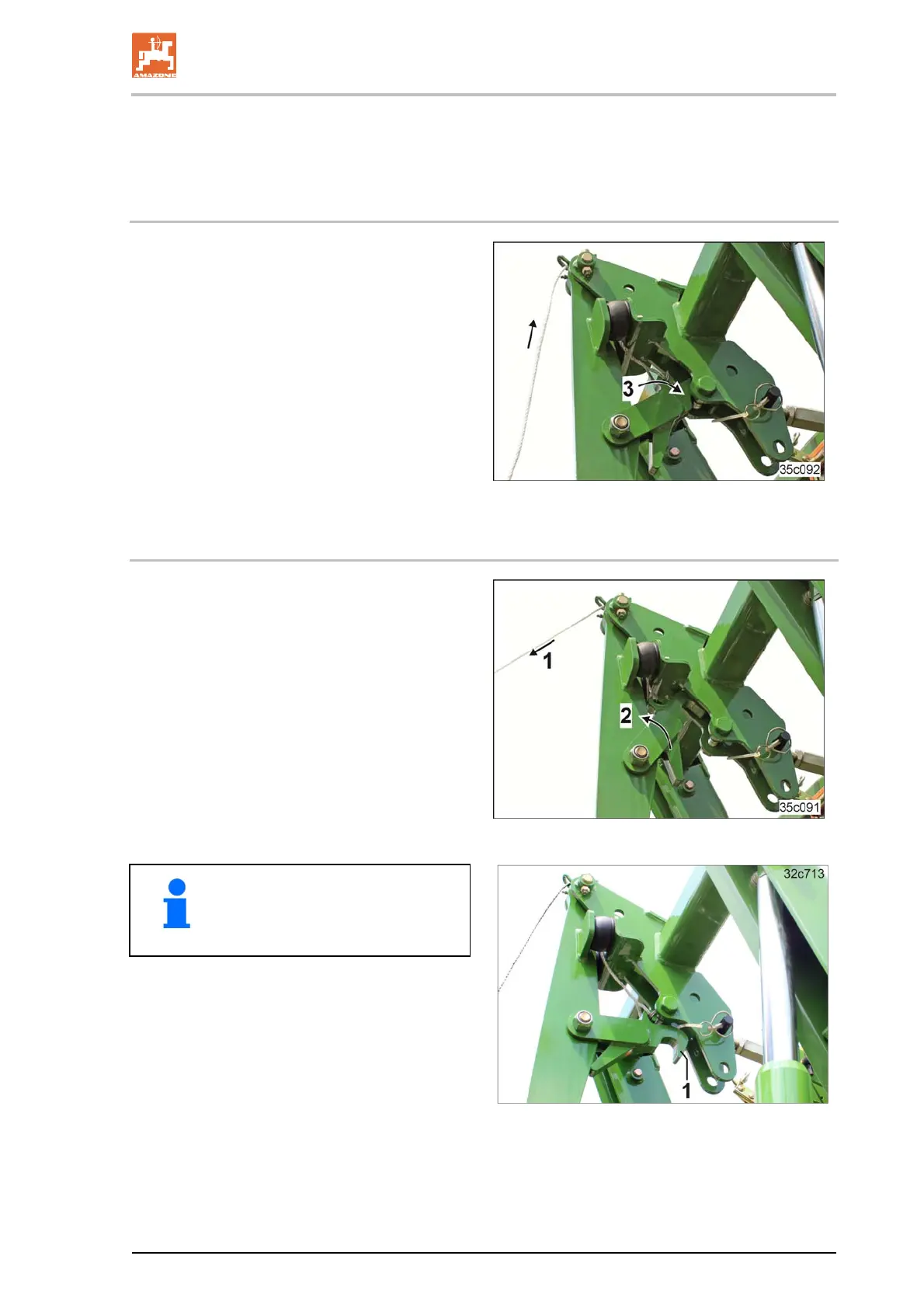
The locking hook (Fig. 131/3) represents
the mechanical locking mechanism of the
lifting frame.
Fig. 131
8.7.2 Unlocking the lifting frame
1. Instruct any people in the area to stand at a
minimum distance of 10.0 m from the
implement.
2. Pull on the cord (Fig. 132/1).
The locking hook (Fig. 132/2) opens.
3. Actuate the tractor control unit
(green).
The lifting frame is lowered.
Actuate tractor control unit
(green) until the
lifting frame is fully lowered.
Fig. 132
If the lifting frame fails to lock, e.g.
when turning at the end of a field
(see Fig. 133), do not pull the cord
(Fig. 132/1).
Fig. 133
 Loading...