Appendix A – PCM Operations (18-0037) AM8a Instruction Manual
February 10, 2000 0037-S0A.L_
A-6
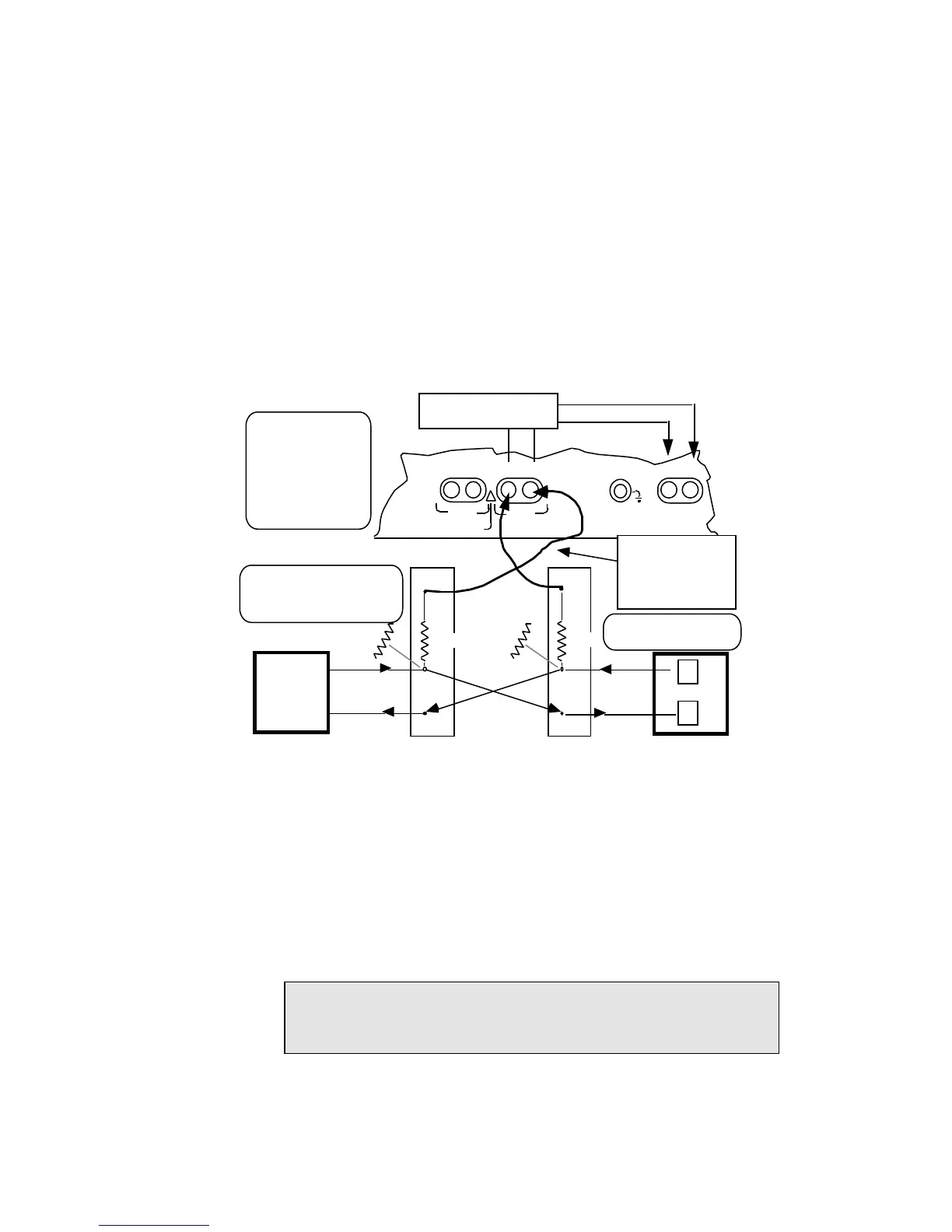
LOOP TIMSTRUNK INPUTS
PCM2
PCM1
!
CAUTION: 10 VOLTS MAX
TXRX
TX/2W RX
TX RX A/B
ON or OFF connection
and straight thru or
reversed TX and RX
connections to TIMS
TX/2W and RX jacks by
the TIMS ([SHIFT] [#,
ST]) key (three positions)
Internal Channel Selection
for monitoring.
channel
RX or TX Channel selected
for monitoring at AM8a
n
n
Do not Remove
Cross Connects
The AM8a IMITATE parameter
will usually be set to the end of
equipment being monitored.
MON
MON
IN IN
100 Ω
100 Ω
860 Ω
860 Ω
Use 48-0131AY cable
(to RX jack only) if
860 Ω resistance (two
430 Ω resistors) is not
in Monitor jack circuit.
Monitor Connections –
PCM1 shown. PCM2 monitoring would make connections to PCM2 jacks
Network Equipment
Network Equipment
Figure A-5. Monitor PCM Connection Points
A.1.2 CIRCUIT CONFIG Menu Settings
The ANALOG/PCM parameter will be set to:
• 1 –pcm int. clk: 1.544 Mbps clocking will originate with the AM8a from the TX
jack to the equipment under test (Figure A–5).
• 2 –<pcm loop clk>: clocking from the equipment under test will control the
AM8a clocking via the RX jack.
NOTE: With either "rpt 1 to 2" or "rpt2 to 1" drop and insert tests, the signal
with the clocking data must come into the PCM1 RX jack. Also refer
to CAUTION concerning order of jack connections.