Front Panel Operation (18-0037) AM8a Instruction Manual
February 10, 2000 0037-S01.L_
1-14
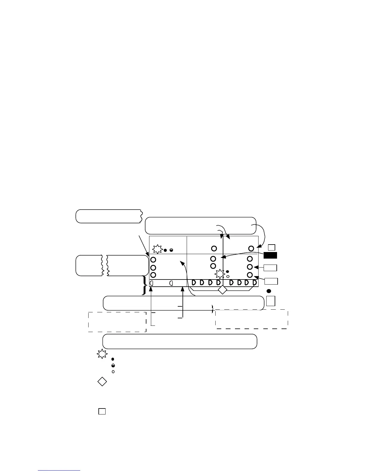
1.8 SIGNALING STATUS LEDs
The Signaling Status LEDs show the TRUNK TYPE that the AM8a is IMITATING and whether it
is operating as an analog terminal/line or switch, or as a PCM terminal. Figure 1-3 shows
these indicators and identifies the menu parameters which set up the operation (see Section 2
sub-sections for appearance of menus and more information on the parameter selections). For
more information on the signaling keys shown in the figure, refer to 1.6.
T+R–
T–R+
RINGING
TRUNK /SLC
®
TYPE
E&M/SLC
®
OFFHOOK
EMULATEEMULATE
a b c
PCM2 PCM1
GND ST/SF
a b c d
LOOP/DID
R-GND
E
M
/
TERMINAL/LINE
SWITCH
T-GND
Te/Line
MODE
CONFIG:
IMITATE
CIRCUIT
CONFIG:
pcm int clk
pcm loop clk
ANALOG/PCM
(see 2.2.2)
PCM
CONFIG 1:
FRAMING
(see 2.3.1
- 2.3.4)
PCM
CONFIG 2:
INPUT
(see 2.3.5)
(see 2.1)
MODE
emulate
monitor
SLC
®96 I
SLC
®96 II
D3/D4
ESF
pcm 1 on
pcm2 on
rpt 1 to 2
rpt 2 to 1
OFF HK a/b ON HK a/b
auto
0/0
.
.
.
X/1
TRUNK :
CONFIG :
TRUNK TYPE
E & M 4W
E & M 2W
DID
SF
loop
ground
Switch
(see 2.4)
analog
When SLC®96 I or II is selected,
E&M/SLC indicator will flash.
MODE must be monitor.
{
PCM selections have no
effect on operation if
CIRCUIT is analog
SEIZE
= lit
= flashing
= not lit
panel legends for LEDs
a, b, c, d LEDs indicate signaling bits for the PCM CHANnel
selected. They will scroll if there is no frame sync (see Section 6, sub-
sections 6.9 and 6.10 for meter display of frame sync and bits). When
frame sync is established, bits will be lit in patterns to indicate
CHANnel conditions.
L
s
s
Typical switch actions resulting in LED indication as condition is
detected. See sub-section 1.6 for more information.
LEDs indicate unit configuration based on menus
*
KP
INPUT
RING
REV
d
L
1
CHAN
auto
0/0
.
.
.
X/1
ZERO SUP
AMI
Figure 1-3. Signaling Status LEDs