AM8a Instruction Manual (18-0037) Meter Display
0037-S06.L_43 February 10, 2000
6-3
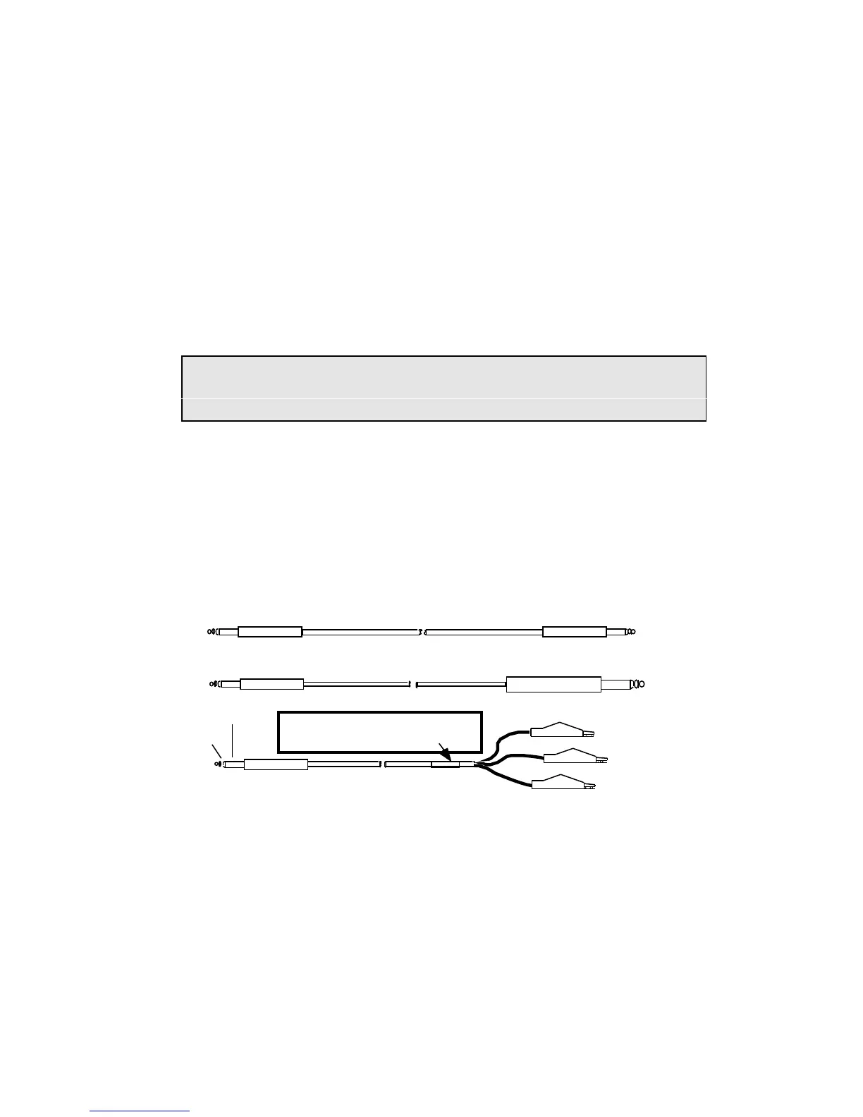
NOTE: Color codes for clip leads on 48-0062 cables have been revised from previous
issue to show cables manufactured after 7 May 1992. Further information on
Figure 6-1.
Figure 6-4 shows the PCM1 and PCM 2 Connections. Because PCM connections at a CO are
usually brought out to jacks for Bantam or 310 plugs, plugs are shown in this figure.
There are Pins on the rear panel DB-24F Connector, labeled LINE/TIMS, that correspond to the
contacts on the front panel jacks. In Figures 6-2 through 6-4 these pin numbers are shown
circled for ease of reference. There is also a rear panel binding post labeled CO GROUND in
addition to the connections on the LINE/TIMS connector.
Rear-panel connections allow the user to "hard-wire" the AM8a into an exchange. The user
must provide a cable wired to a matching DB 24M connector if the LINE/TIMS connector is to
be used. A view of the rear panel (and connector pin identifications) is shown in Section 7.
tip
ring
sleeve
CABLE 48-0062, 6 FT.
BANTAM PLUG
BANTAM PLUG
BANTAM PLUG
BANTAM PLUG
310 PLUG
CABLE 48-0047, 6 FT.
CABLE 48-0048, 6 FT.
BLACK (Sleeve—g)
GREEN (Tip— t)
RED (Ring — r)
NOTE: Cables manufactured before 5/7/92
are Green (Ring - r) and RED (Tip - t) and
will not have this color-code label
Figure 6-1. Cables for AM8a Front Panel Test/Meter Connections