Meter Display (18-0037) AM8a Instruction Manual
February 10, 2000 0037-S06.L_
6-18
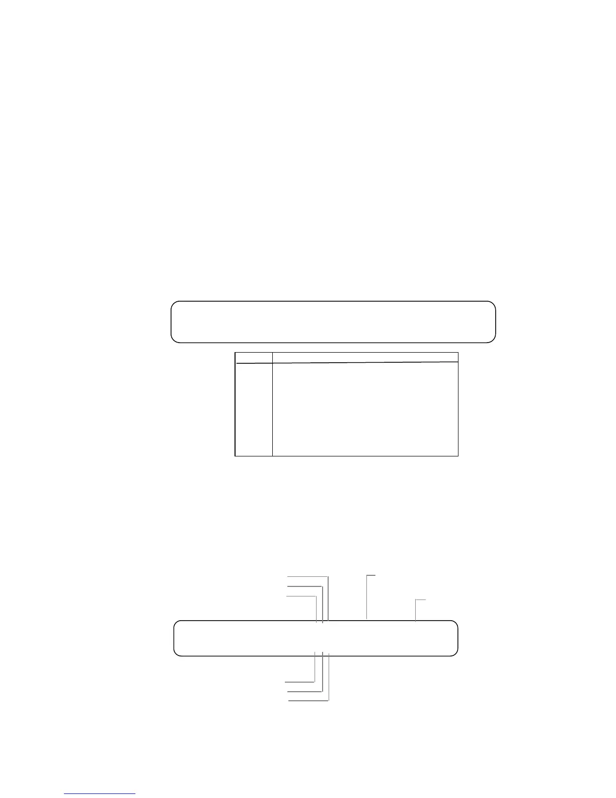
6.11.2 PROTECTION TX or RX: provides an indication of protection settings for the link.
Figure 6-7 shows the display and interprets the conditions represented by the "0" or
"1" states of the display.
PROTECTION TX
PROTECTION RX
1111
1111
1111
1110
1101
1100
1010
0101
0100
0010
IDLE
SWITCH LINE A RECEIVE
SWITCH LINE B TRANSMIT
SWITCH LINE C TRANSMIT
SWITCH LINE D TRANSMIT
SWITCH LINE B TRANSMIT & RECEIVE
SWITCH LINE C TRANSMIT & RECEIVE
SWITCH LINE D TRANSMIT & RECEIVE
Message
display
Figure 6-7. SLC®96 Alarm Conditions Meter Display
6.11.3 MAINTENANCE TX or RX: provides a display of status of maintenance messages for
the link. The interpretation of the RX and TX displays depends upon whether the unit
is functioning as a te/line (RT) or as a switch (LDS).
Figure 6-8 shows the display, and interprets the conditions represented by "0" or "1"
states for either direction. This display also shows the channels and time-slot
assignments during the test operation.
MAINTENANCE TX
MAINTENANCE RX
111
000
1=RX/TX Message from LDS to RT
RX/TX Message from RT to LDS1=
SEIZE
PROCEED RC
TEST ALARM RC
LDS means Local Data Switch
RT means Remote Terminal
NOTE:
0=No message
0=No message
CHNL=xx TS=xx
CHNL=xx TS=xx
TEST ALARM CR
PROCEED CR
ON HOOK
Time Slot
Channel Test
00= inactive
01 - 48 = Channel
00= inactive
01 - 24 = Time Slot
Figure 6-8. SLC®96 Alarm Conditions Meter Display