Meter Display (18-0037) AM8a Instruction Manual
February 10, 2000 0037-S06.L_
6-6
5
6
PCM 1
RX
PCM 1
TX
7
8
(R)
(T)
(R1)
(T1)
RX 1 dBdsx
NOISE
RX t–r
NOISE
TX t–r
Repeat (1)
Repeat (1)
n. c.
tip
ring
n. c.
tip
ring
TX1 TONE
RX1 TONE
PCM TX/RX FRAME SYNC
PCM 1 BPV...BLUE
TX or RX a, b bits
RX 2 dBdsx
PCM 2
RX
n. c.
tip
ring
PCM 2
TX
(R)
(T)
3
4
1
2
(R1)
(T1)
PCM TX/RX FRAME SYNC
PCM 2 BPV...BLUE
TX or RX a,, b bits
TX t–r
NOISE
RX t–r
NOISE
Repeat (2)
Repeat (2)
n. c.
tip
ring
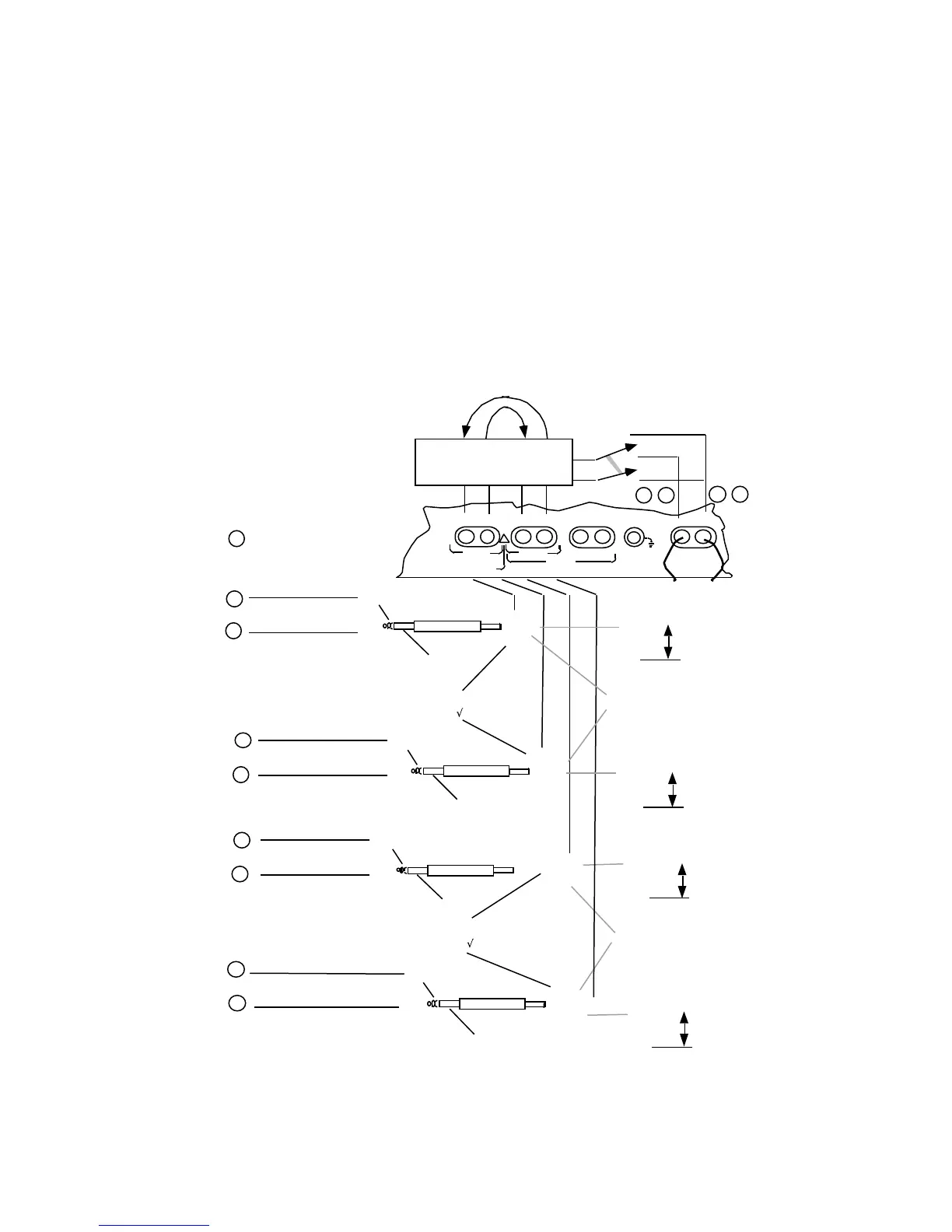
are pin numbers on
rear panel LINE/TIMS
connector.
n
TX2 TONE
RX2 TONE
Select CHANnel
0, 1 to 24; -1 to -96, -97 *
Select CHANnel
0, 1 to 24; -1 to -96, –97 *
Select CHANnel
0, 1 to 24; -1 to -96, –97 *
Select CHANnel
0, 1 to 24; -1 to -96, –97 *
SLC
ç ALARM, PROTECTION,
MAINTENANCE for SLC
96
* CHANnel –97 to monitor SLC®96 II Activity Messages on 4Kbps data channel
LOOP
TIMS
TRUNK INPUTS
CAUTION: 10 VOLTS MAX
E & M
PCM2
TX RX TX/2W RX E/M SB/SG
PCM1
TX/2W
RX
!
T/R
To TIMS TX/2W
RX Jack s
Internal CHANnel Selection and
De-multiplexing. Z for TIMS is
set by IMPEDANCE menu.
ON, OFF, REVerse connection made to TIMS
Jacks by the TIMS key ([SHIFT] [#, ST])
•
•
•
•
•
•
on
off
•
•
RX
TX
rev (monitor only)
For rpt 1 to 2 or rpt 2 to 1: Unselected
channels are passed in MODE emulate.
All channels are passed in MODE monitor.
19
20 17 18
SLCç ALARM, PROTECTION,
MAINTENANCE for SLC
96
Figure 6-4. PCM T1/SLC®96 Test/Meter Front Panel Connections