AM8a Instruction Manual (18-0037) Appendix A – PCM Operations
0037-S0A.L_54 February 10, 2000
A-7
LOOP
PCM2 PCM1
TIMS
TRUNK INPUTS
!
CAUTION: 10 VOLTS MAX
TXRX
TX/2W RX
TX RX A/B
Internal Channel Selection for
Emlulation and Drop-Insert (Rpt)
voice channel
Emulate PCM1 or PCM2
and
Repeat 1 to 2 or Repeat 2 to 1 connections
1.544Mbps clock source
for rpt 1 to 2 or rpt 2 to 1
n
n
n
n
ON or OFF connection
to TIMS TX/2W and RX jacks by
the TIMS ([SHIFT] [#, ST]) key
The AM8e IMITATE
parameter will
usually be set to the
end of equipment
being monitored.
For rpt 1 to 2 or rpt
2 to 1: Unselected
channels are passed
in MODE emulate.
All channels passed
in MODE monitor .
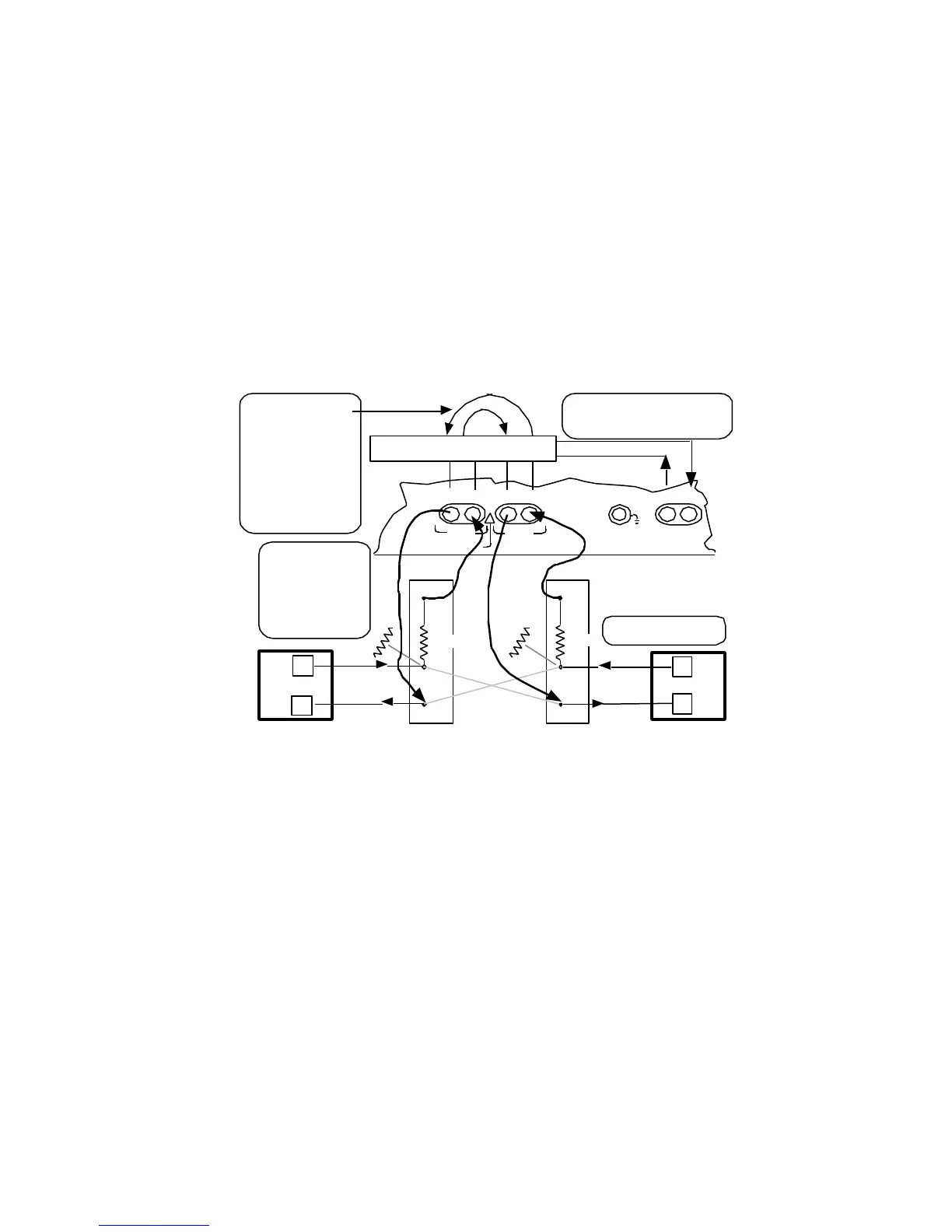
CAUTION: To avoid
line "hits" make RX
connections to MON
jacks, make the TX
connections, then
make the IN
connections.
Network Equipment
Network Equipment
IN
MON
100 Ω
MON
860 Ω
860 Ω
IN
100 Ω
(IN jacks break
cross connects)
Figure A-6. Emulate and Repeat (Drop and Insert) PCM Connections
A.1.3 PCM CONFIG 1 and CONFIG 2 Menu Settings
The INPUT parameter will be set to:
• 0 –<pcm 1 on>: circuitry of AM8a is connected to the PCM1 RX and TX jacks
(Figures A-1, A-2, and A-6).
• 1 –pcm2 on: circuitry of AM8a is connected to the PCM2 RX and TX jacks
(Figures A-1, A-2, and A-6).
• 2 –rpt1 to 2: circuitry of AM8a is connected to provide a path from PCM1 to
PCM2 jacks (RX to TX) in both directions. In emulate mode, a single T1 voice
channel may be dropped from the other 24 channels for tests. For the selected
channel (see Figures A-3 and A-6):
• TX path toward PCM2 is idled; RX path from PCM2 is ignored.
• TX path toward PCM1 is emulated; RX path from PCM 1 is analyzed.