AM8a Instruction Manual (18-0037) Table of Contents
0037-TOC.L_58 February 10, 2000
xiii
List of Figures
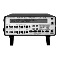
Figure 1-1. AM8a Front Panel......................................................................................................... 1-1
Figure 1-2. AM8a Events Display ................................................................................................... 1-4
Figure 1-3. Signaling Status LEDs................................................................................................ 1-14
Figure 6-1. Cables for AM8a Front Panel Test/Meter Connections............................................... 6-3
Figure 6-2. Loop/Ground Start and DID Analog Test/Meter Front Panel Connections..................6-4
Figure 6-3. E & M and SF Test/Meter Front Panel Connections.................................................... 6-5
Figure 6-4. PCM T1/SLC®96 Test/Meter Front Panel Connections.............................................. 6-6
Figure 6-5. SLC®96 Mode 1 Channel Number to Time Slot Assignments..................................6-16
Figure 6-6. SLC®96 Alarm Conditions Meter Display..................................................................6-17
Figure 6-7. SLC®96 Alarm Conditions Meter Display..................................................................6-18
Figure 6-8. SLC®96 Alarm Conditions Meter Display..................................................................6-18
Figure 7-1. Event-only Printout..................................................................................................... 7-16
Figure 7-2. Events & Details Printout (Monitor Mode)..................................................................7-17
Figure 7-3. Events & Details Printout (Emulate Mode)................................................................. 7-18
Figure 7-4. Manual Short Print (Meter Display Example)............................................................. 7-18
Figure 7-5. Manual Short Print (EMULATE Analog Switch, Te, PCM Examples)........................7-19
Figure 7-6. Manual Long Print (Meter Display Example) ............................................................. 7-20
Figure 7-7. Manual Long Print (Setup Example).......................................................................... 7-21
Figure 7-8. AM8a Rear Panel Connections..................................................................................7-24
Figure 7-9. RS232 Printer Cable ..................................................................................................7-25
Figure 7-10. RS232 Chaining Cable............................................................................................. 7-25