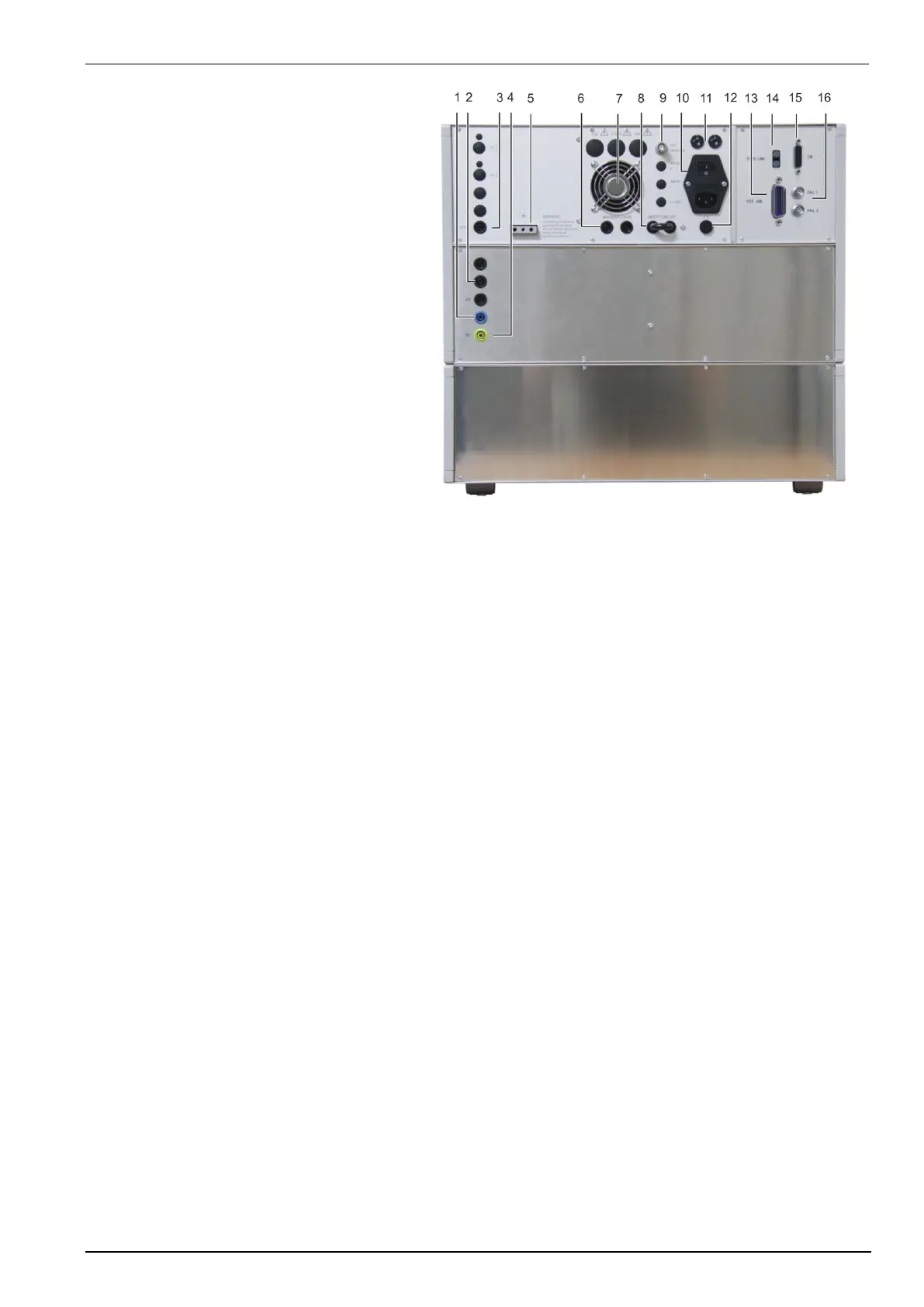
9 External trigger
10 Power on switch and fuse
11 Mains selector 115V / 230V
12 Fuse of the high voltage power supply
13 Parallel interface IEEE
14 Optical interface (USB)
15 Remote control connector
16 FAIL 1 / FAIL 2 connector
9 External trigger (BNC plug)
Trigger input for a pulse release. Trigger level 5-15V positive going.
10 Power on switch
The switch is part of the mains filter. Mains fuses are part of the filter. (230V / 1A and 115V / 2A)
11 Mains selector
Selection of 115V / 230V
12 Fuse of the high voltage power supply
The high voltage power supply is protected by this fuse „F3“. In case that no high voltage is generated but the
control unit works properly this fuse shall be checked.
13 Parallel interface GPIB / IEEE 488
IEEE 488 interface with IEEE connector
14 Optical interface (USB)
For data transfer an optical USB interface is available. The user must set the same Baud rate in the device and
control software. (Default setting 9600 baud).
When the interface is not used, the input and output must be closed by the delivered sticks. Otherwise unwanted
light can start an interrupt on the optical input circuit.
15 Remote control connector CN
External coupling devices are controlled via this remote control connector.
16 Fail detection FAIL 1 EUT control (TEST STOP)
Grounding this input will cause a complete stop of the running test procedure. (+15V to ground) The test must
be completely restarted.
Fail detection FAIL 2 EUT control (TEST PAUSE)
Grounding this input will cause a break for the running test procedure (+15V to ground).The test will be
continued when the input is no more connected to ground.
 Loading...