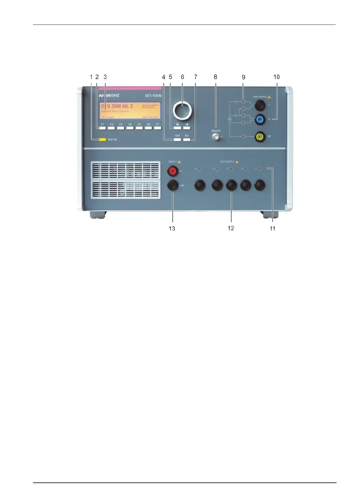
9 LED coupling 1 ph. version
10 EUT test supply L, N, PE 1ph version
11 LED coupling 3 ph. version
12 EUT test supply 3-phase version
13 Direct output HV – COM
1 Test On
By pressing the key "Test On" the power supply of the high voltage part will be ready for start. The red LED indicates the
trigger of a burst event.
2 Function keys "F1 .. F7
Parameters and functions, displayed in the lowest line, can be selected with the related function key.
3 Display
All functions and parameters are displayed (8 lines with max. 40 characters).
4 Exit
Pressing of the Exit function will cause a reset of the firmware. This is only possible if no test routine is running.
5 Cursor keys
Parameters and functions can be changed on-line. The selection of these parameters is realized with the cursor moving to
the left or to the right.
6 Knob (Inc. / Dec)
The knob increments or decrements test parameters with a numeric value or selects from a list of parameters.
7 ESC
When pressing the ESC button the user moves back one page in the menu. The displayed parameters before are stored.
8 Trigger output
At the BNC output the generator trigger can be used as oscilloscope trigger output. It is synchronous to the impulse events.
9 LED coupling
The LED Indicates the actual coupling mode for the 1-phase version.
10 EUT test supply
For single-phase EUT the coupling/decoupling network is part of the generator. The EUT is powered via the safety banana
plugs at the front panel of the simulator
 Loading...