EasyManuals Logo

Ametek OCS 500N6 Series User Manual

Ametek OCS 500N6 Series
80 pages
To Next Page IconTo Next Page
To Previous Page IconTo Previous Page
Page #64 background imageLoading...
Page #64 background image
AMETEK CTS OCS 500 N6 series
Manual for Operation V 5.24 64 / 80
10.3.
Verification Ringwave
10.3.1.
Verification Parameter
IEC 61000-4-12, ANSI C62.41 (open circuit)
V peak open circuit voltage ±10%
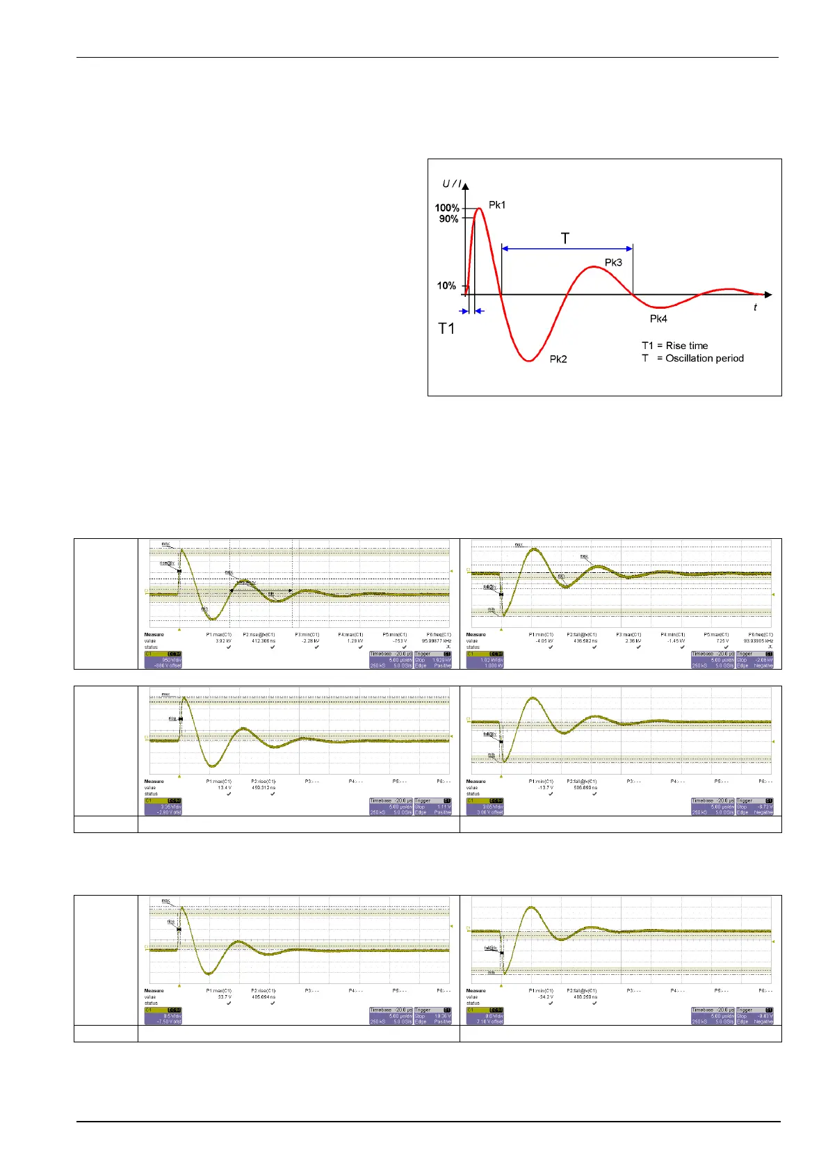
Rise time first peak 0.5 μs ±20%
Oscillating frequency 100 kHz ±10%
Decaying of peak 2-1 40% to 110%
Decaying of peak 3-2 40% to 80%
Decaying of peak 4-3 40% to 80%
(Short circuit)
I peak (12) 333.33A ±10%
I peak (30) 133.33A ±10%
Rise time first peak 0.2 to 1.0 s
Oscillating frequency 100 kHz ±10%
Impedance 12 / 30 ±20%
Remark: The output impedance is calculated result of the ratio of the first peak open circuit voltage and the
first peak short current, measured with a 4000V pulse.
Typical pulses, measured with a calibrated equipment
Ringwave coupling L1 N impedance = 30
Open
circuit
Short
circuit
U set : +4000V
U set : -4000V
Ringwave coupling L1 N impedance = 12
Short
circuit
U set : +4000V
U set : -4000V

Table of Contents

Questions and Answers:

Question and Answer IconNeed help?

Do you have a question about the Ametek OCS 500N6 Series and is the answer not in the manual?

Ametek OCS 500N6 Series Specifications

General IconGeneral
BrandAmetek
ModelOCS 500N6 Series
CategoryTest Equipment
LanguageEnglish

Related product manuals