AMETEK CTS OCS 500 N6 series
Manual for Operation V 5.24 49 / 80
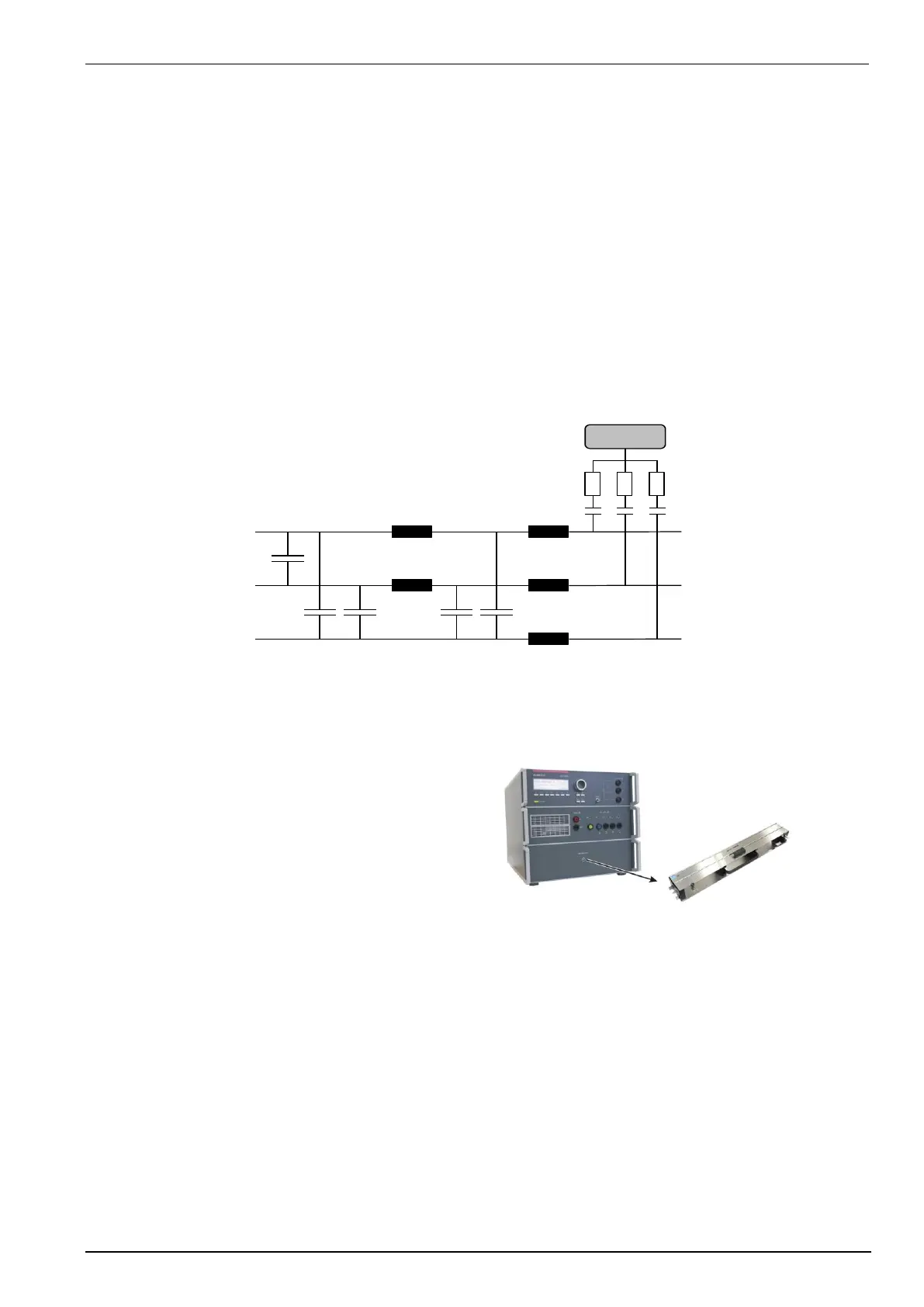
Coupling decoupling network
The decoupling part of the coupling network has to:
- filter the interference pulses in the direction to the power supply;
- protect other systems that are connected to the same power supply and
- realize a high impedance of the power supply, e.g. battery supply.
Coupling/decoupling network for ac/dc power lines
The coupling network has to couple the interference pulses to the lines of a power supply system (AC or DC). As
coupling devices capacitors of sufficient strength and bandwidth shall be used according to IEC 61000-4-12 / -18.
Line => GND
Neutral => GND
The PE line to the EUT is decoupled via an inductance from the power supply.
The test pulse is coupled direct to the PE line on the EUT direction
Koppelnetzwerk gem. IEC 61000-4-12
Coupling to Signal and Datalines
For coupling the fast damped oscillatory wave to signal
and data lines the user must use the capacitive
coupling clamp HFK. It is the same clamp as used for
EFT/burst test as per IEC 61000-4-4 for coupling to
signal and data lines.
The generator signal output is located at the front side
of the OCS 500N6F
 Loading...