Mechanical Specifications
TM-F1OP-C1XN-01 A-11
Mechanical Specifications
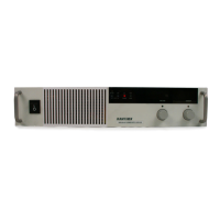
Front Panel V and I Control 10-turn voltage and current potentiometers
Front Panel Voltage Control
Resolution
0.02% of maximum voltage
Front Panel Voltage and Current
Meters
3.5-digit green numeric LED displays. For accuracy
specifications, see Table A-1 and Table A-2.
AC Input Connector Type 3-terminal 34 A, 250 V, right angle, PC mount, wire clamp
connector with removable strain relief cover
Input Fuses
a
a. Fuses are located on the A4 PCB (printed circuit board). The fuses are
NOT operator-replaceable.
1 A, 250 V, 5 x 20 mm slow fuse (T), location: F34;
2 A, 250 V, 5 x 20 mm time delay (T), location: F95;
10 A, 250 Vac, 5 x 20 mm fast high interrupt (F), location: F29;
30 A, 300 Vac, 10.3 x 41.3 mm medium time lag (T), locations:
F2, F4.
Output Connector 6 V to 40 V models: nickel-plated copper bus bars with
removable bus bar shield; bus bar holes: 0.332 in. (8.17 mm)
diameter (D) (1), 0.197 in. (5.0 mm) D (2);
60 V to 600 V models: 4-terminal wire clamp connector.
Sense Connector 5-terminal wire clamp connector (2 piece)
Analog Programming Connector 15-terminal wire clamp connector (2 piece)
Chassis Ground Two chassis ground screws located on rear panel for bonding
connections
Cooling Fan cooled. Air exhausts to rear. Over temperature shutdown:
automatic restart or latch off (switch-selectable).
Mounting Rack mount ears integral to the front panel.
Weight Approximately 18 lb. (8.2 kg)
Approvals CE mark: Meets EMC standards EN50081-2 and EN50082-2
and safety standard IEC1010-1
c(UL)us: UL certified to UL3111-1, 1st edition and to CAN/
CSA C22.2 No. 1010.1-92
FCC: Meets Class A limits of Part 15 subpart B
TM-F1OP-C1XN-01.book Page 11 Thursday, October 25, 2007 9:04 PM
 Loading...