- 10 -
3378702_ATE_inst_GB ENGLISH
GB
ELECTRICAL CONNECTION
Caution - Warning
The connection must be made by authorised, skilled personnel, in accordance with the
relevant legal requirements, using appropriate and speci ed materials.
The appliance is supplied with operating voltage of 400V/3N/PE which can be switched to
230V/3/PE (only for models AT 61-101-201).
The appliance is supplied with operating voltage 400V/3N/PE, which cannot be switched
to other values (only for models AT 82-122-202) (see attached wiring diagrams).
Before doing any work, cut o the mains electricity supply.
A
B
C
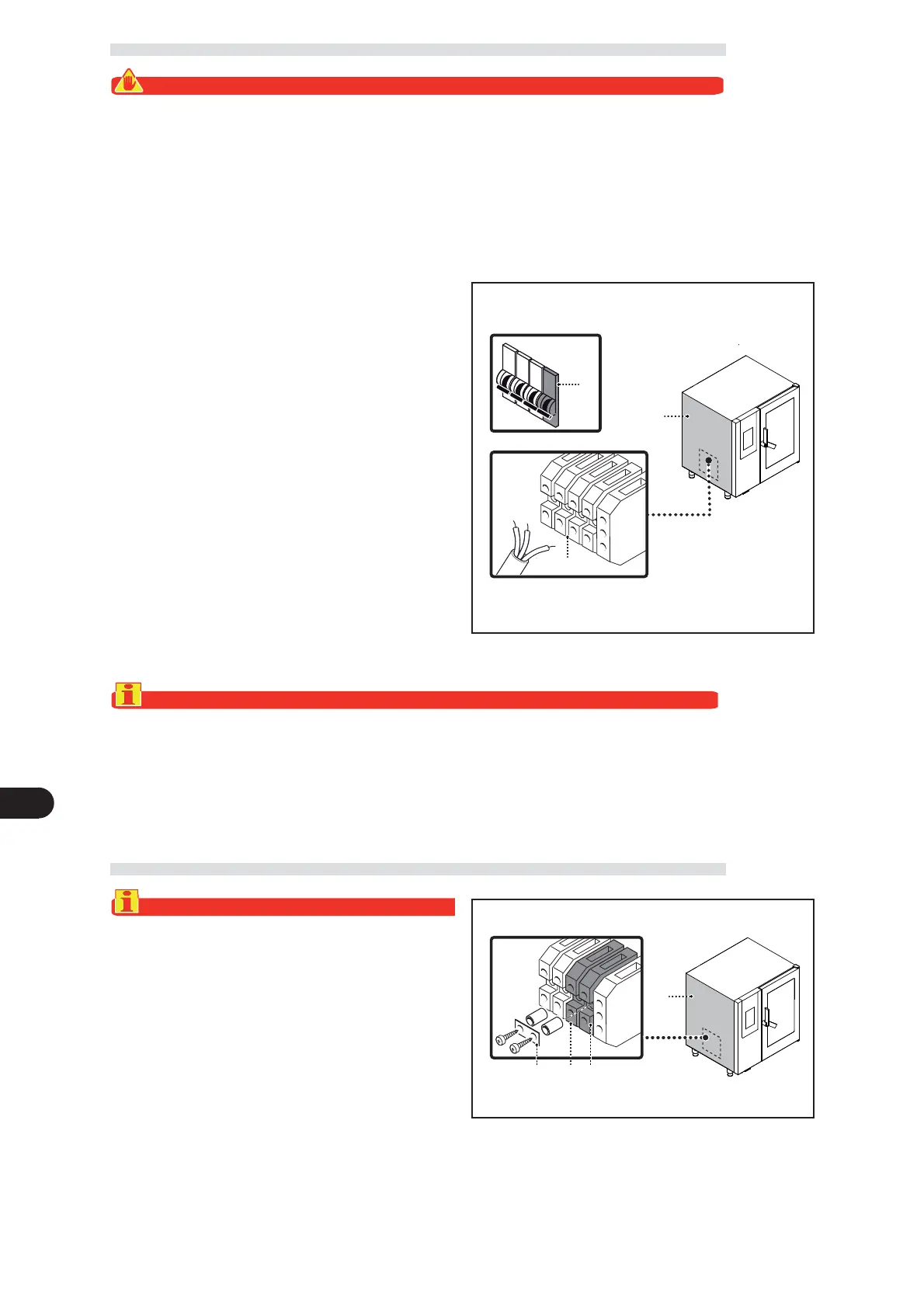
Important
When connecting, take care to connect the neutral and earth lines.
) Replace the panel and retighten the screws when the operation is complete.
Connect the appliance to the mains electricity supply
as follows.
) If not already present, install an automatic circuit-
breaker (B), protecting only each single appliance
and located close to it, with the following charac-
teristics.
– Thermal breaker device (to adjust see table on page
3 of user instruction manual).
– Di erential breaker set at 30 mA
– Classe B o C (IEC 898)
) Undo the screws and remove the side panel (A).
) Connect the automatic circuit-breaker (B) to the
appliance’s terminal board (C) and to the electri-
cal mains supply, in accordance with the electrical
system diagram provided at the back of the manual
and using a cable with the following characteristics.
– Weight: ≥
than H05RN-F type (designation 245 IEC
57).
– Temperature of use: ≥70°C.
CONVERSION OF ELECTRICITY SUPPLY AT61101201
Important
The appliance is supplied at an operating voltage
400V/3N (indicated on the sticker applied to the
dataplate); conversion to 230V/3 can be carried
out as described below.
To carry out this operation, proceed as follows.
) Disc
onnect the mains electricity supply.
) Undo the screws and remove the side panel (A).
) Fit the jumper (B) to make the electrical connec-
tion of the terminals (C-D) (see attached wiring dia-
grams).
A
B C D

 Loading...