Chapter 5 — Assembly Replacement 5-5 Spectrum Analyzer Module Assembly Replacement
MS2720T MM PN: 10580-00342 Rev. D 5-7
5-5 Spectrum Analyzer Module Assembly Replacement
This procedure provides instructions for removing and replacing the Spectrum Analyzer PCB Assembly.
The Spectrum Analyzer Module Assembly is located in the back half of the case and includes the Top
Connector Panel.
1. Open the case as described in Section 5-3 “Opening the Spectrum Master Case”.
2. If the unit has Option 809 or 813 or 820 then remove the Tracking Generator Module Assembly as
described in Section 5-4 “Tracking Generator Module Assembly Replacement ”.
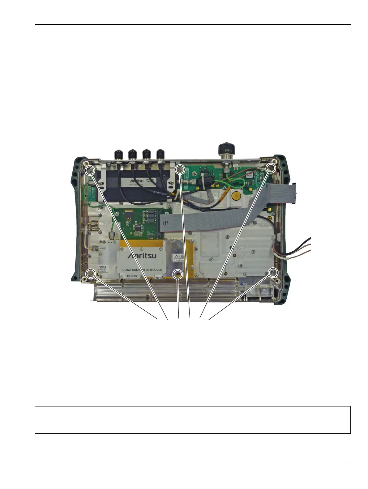
3. Use a Torx T10 screwdriver to remove the six screws securing the Spectrum Analyzer Module Assembly
to the back half of the instrument case (Figure 5-6).
4. Carefully lift up and remove the Spectrum Analyzer PCB Assembly and attached Top Connector Panel.
5. Reverse the above steps to install the new Spectrum Analyzer PCB Assembly.
6. You will need to transfer the top connector panel RF Out N connector in addition to the Tracking
Generator Module Assembly on units that have Option 809 or 813 or 820 installed.
Figure 5-6. Spectrum Analyzer PCB Assembly
Note
There is an RF gasket material between the two halves of the case, and in the connector panel
grooves. Take care not to remove or damage this material when removing or replacing the
Spectrum Analyzer Module and connector panel assembly.

 Loading...


