3-3 Option 809, 813 or 820 Tracking Generator Verification Chapter 3 — Options Verification
3-6 PN: 10580-00342 Rev. D MS2720T MM
Tracking Generator Power Accuracy Verification
Setup
Setup
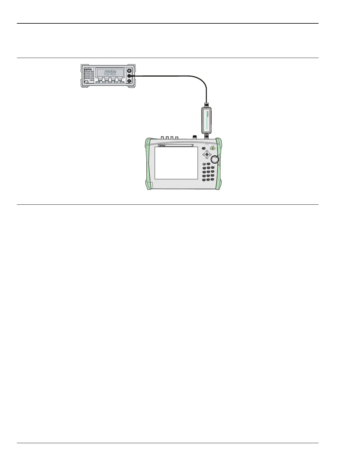
1. Install the MA2442D power sensor to the power meter and calibrate the sensor.
2. Connect the MA2442D power sensor to the Generator RF Output connector of the MS2720T.
3. Set the sensor calibration factor frequency to 50 MHz.
4. Set the Center Frequency of the MS2720T to 50 MHz, and set the Span to 0 Hz.
5. Press Shift, then press the Measure (4) key, and then press Generator.
6. Press the Output Power soft key to set the tracking generator to 0 dBm.
7. Set the Generator Mode is set to Tracking.
8. Press Generator Output to toggle the tracking generator ON.
9. Record the power sensor reading into the “Measured Power” column of Table A-65, “Tracking Generator
Level Accuracy” on page A-34
10. Verify that the sensor reading is within specification.
11. Reduce the Output Power (Test Level) setting of the tracking generator to the next power level in
Table A-65 on page A-34.
12. Repeat the power measurement for every Output Power (Test Level) in Table A-65.
13. Change the MS2721B Center Frequency to match the Frequency in the next test record in Appendix A,
which is Table A-65, “Tracking Generator Level Accuracy” on page A-34.
14. Set the power sensor calibration factor frequency to the same frequency.
15. Repeat the measurements for all frequencies and power levels shown in the test records of Table A-65,
for units with Option 809 the last test point is at 8950 MHz @ -40 dBm, for units with Option 813 the last
test point is at 12950 MHz @ -40 dBm and for units with Option 820 the last test point is at 17950 MHz
@ -40 dBm.
Figure 3-3. Tracking Generator Power Verification
Power
MS2720T
Spectrum Analyzer
SpectrumMaster
Charge
File
7
System
8
Shift
Esc
Mode
9
Meas
4
Trace
5
Limit
6
Preset
1
Cal
2
Sweep
3
0
.
+/-
Menu
Enter
MS2720T Spectrum Master
Sensor

 Loading...


