3-8 Option 883, TD-LTE Signal Analyzer Verification Chapter 3 — Options Verification
3-30 PN: 10580-00342 Rev. D MS2720T MM
TD-LTE Channel Power Accuracy Tests
The tests in this section verify the function of the optional TD-LTE Signal Analyzer in Model MS2720T.
Setup
Procedure
1. Connect the Power Sensor to the power meter and zero the sensor.
2. Set the Power Meter Measurement MODE to True RMS, set Averaging MODE to Moving, and set
Averaging NUMBER to 256.
3. Set the calibration factor frequency of the power sensor to 750 MHz.
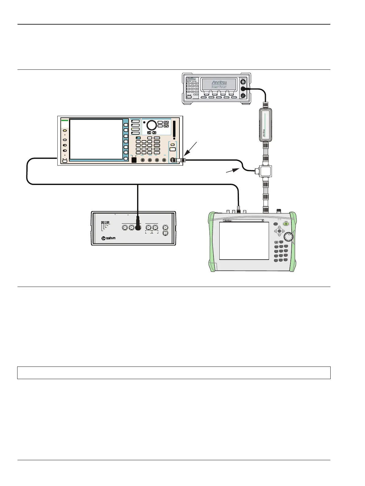
4. Connect the Power Sensor, 1870A splitter, 6 dB attenuators (quantity 2), as shown in Figure 3-10.
Figure 3-10. TD-LTE Signal Analyzer Option Verification
Note The TD-LTE pattern requires a Waveform Data license MX370110A that must be purchased.
MS2720T Spectrum Master
Power
MS2720T
Spectrum Analyzer
SpectrumMaster
Charge
File
7
System
8
Shift
Esc
Mode
9
Meas
4
Trace
5
Limit
6
Preset
1
Cal
2
Sweep
3
0
.
+/-
Menu
Enter
MS2720T Spectrum Master
MG3700A Vector Signal Generator
Function
Ethernet Control Input Modulation Input
Cursor/Edit
RF Output
3
MG3700
Vector Signal
Generator
250kHz-6GHz
10 MHz Reference
Oscillator Warmup
Oscillator Ready
Failure
1 PPS Sync
1 PPS OUT
1 MHz 5 MHz 10 MH
5 MHz 10 MHz
Sine wave Out AUX
1 PPS IN
Power
TESTIME
PLUS
R
RubiSource T&M
R
10 MHz
Sine Out
ML2438A Power Meter
MA2482D
Power Sensor
1870A
Power Splitter
34NN50A Adapter
6 dB Fixed
Attenuator
6 dB Fixed
Attenuator
34NN50A
Adapter
15NNF50-1.5B
Ext Ref In
(back panel)
Ext Ref In
 Loading...


