5-4 Tracking Generator Module Assembly Replacement Chapter 5 — Assembly Replacement
5-6 PN: 10580-00342 Rev. D MS2720T MM
5-4 Tracking Generator Module Assembly Replacement
This procedure provides instructions for removing and replacing the Tracking Generator Module Assembly.
The Tracking Generator Module Assembly is mounted on top of the Spectrum Analyzer Module Assembly
which are located in the back half of the case and includes the Top Connector Panel.
1. Open the case as described in Section 5-3 “Opening the Spectrum Master Case”.
2. Remove the ribbon cable attached to the Tracking Genrator Module Assembly.
3. Remove the SMA cable attached at the J2 location on the Tracking Generator.
4. Using a 5/16 torque wrench (8 in/lbs) loosen the semi rigid cable connection on the Tracking Generator.
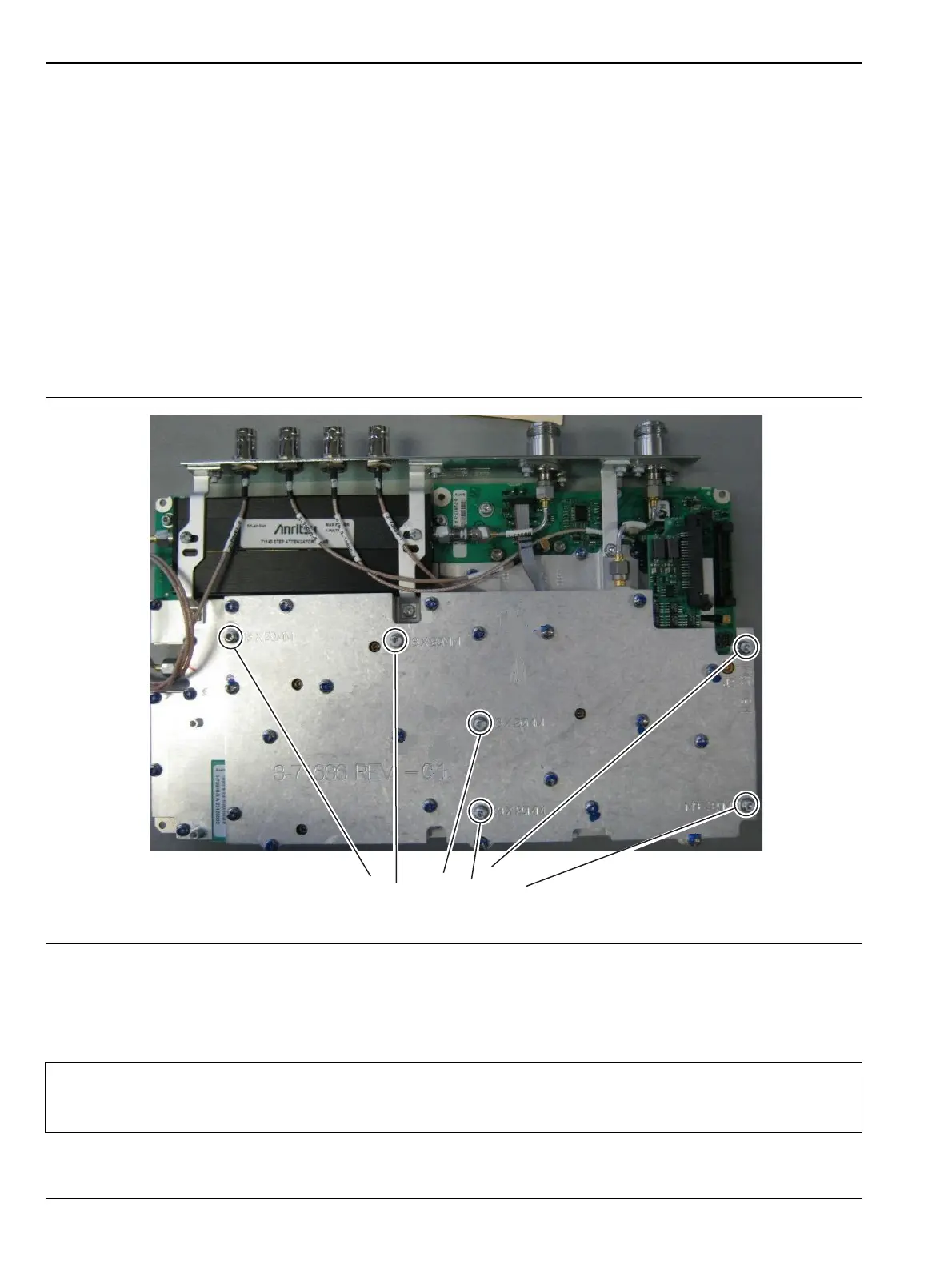
5. Use a Torx T10 driver to remove the six screws, denoted by the M3 x 20 MMstamping on the shield,
securing the Tracking Generator to the Spectrum Analyzer Module Assembly (Figure 5-5).
6. Carefully lift up the Tracking Generator Module Assembly and remove the semi rigid cable loosened in
step 4 to allow the complete removal of the Tracking Generator Module Assembly.
7. Reverse the above steps to install the new Tracking Generator Module Assembly. Take note that there
are bosses on the Tracking Generator shield that must line up with the bosses on the Spectrum Anaylzer
shield.
Figure 5-5. Tracking Generator ModuleAssembly
Note
There is an RF gasket material between the two halves of the case, and in the connector panel
grooves. Take care not to remove or damage this material when removing or replacing the
Spectrum Analyzer Module and connector panel assembly.

 Loading...


