Spectrum Analyzer 2-3 Making Spectrum Analyzer Measurements
Spectrum Analyzer MG PN: 10580-00349 Rev. H 2-5
Zero Span IF output effectively uses the spectrum analyzer as a receiver front-end,
converting the input signal at the spectrum analyzer RF In connector to a signal centered at
140 MHz out of the IF Out 140 MHz connector. You can then process the IF signal in a way
that meets your needs. That may mean using an A-to-D converter or some other signal
processing method. An anti-aliasing filter can be employed in the signal processing to reduce
the effect of noise and spurious signals. A filter centered on 140 MHz with a bandwidth
slightly wider than 32 MHz is also advised to eliminate any undesired out-of-band signals on
the IF output. In particular, signals at 100 MHz and its harmonics (that would be eliminated
by the filter) are on the IF output.
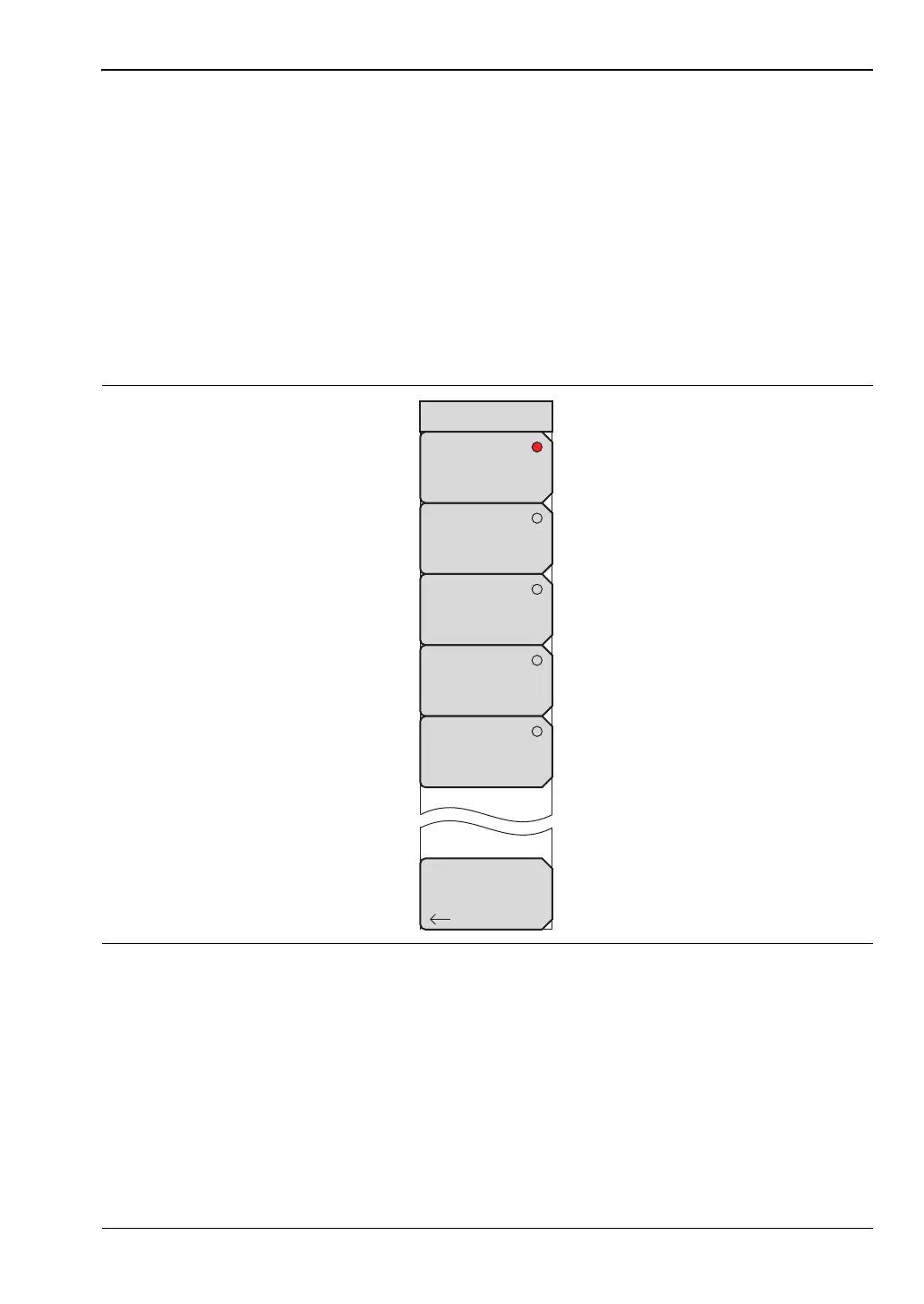
When IF output is turned on by setting the instrument to zero span , then pressing the Zero
Span submenu key a second time displays the Zero Span IF Bandwidth menu (Figure 2-2).
The selectable bandwidth values may differ among instrument types. This figure is typical.
The Normal IF BW choice selects a bandwidth that uses analog bandpass filters in the normal
RBW chain. By changing the RBW, different filter bandwidths are selected.
The spectrum analyzer has several mixer bands. Depending on the operating frequency,
the local oscillator may be above or below the input frequency. When the local oscillator
frequency is below the input frequency, an increase in the input frequency results in an
increase in the IF output frequency. When the local oscillator is above the input frequency, an
increase in the input frequency moves it closer to the local oscillator frequency and the IF
output frequency consequently decreases. Table 2-1 on page 2-6 shows the bands and
indicates where the LO frequency is, in relation to the RF frequency.
Figure 2-2. Zero Span IF Bandwidth Selection Menu
Zero Span IF BW
Back
7 MHz BW
10 MHz BW
16 MHz BW
32 MHz BW
Normal
ООО "Техэнком" Контрольно-измерительные приборы и оборудование www.tehencom.com
 Loading...


