3-8 Interference Mapping Interference Analyzer (Option 25)
3-12 PN: 10580-00349 Rev. H Spectrum Analyzer MG
C. Press the Recall Default Grid submenu key.
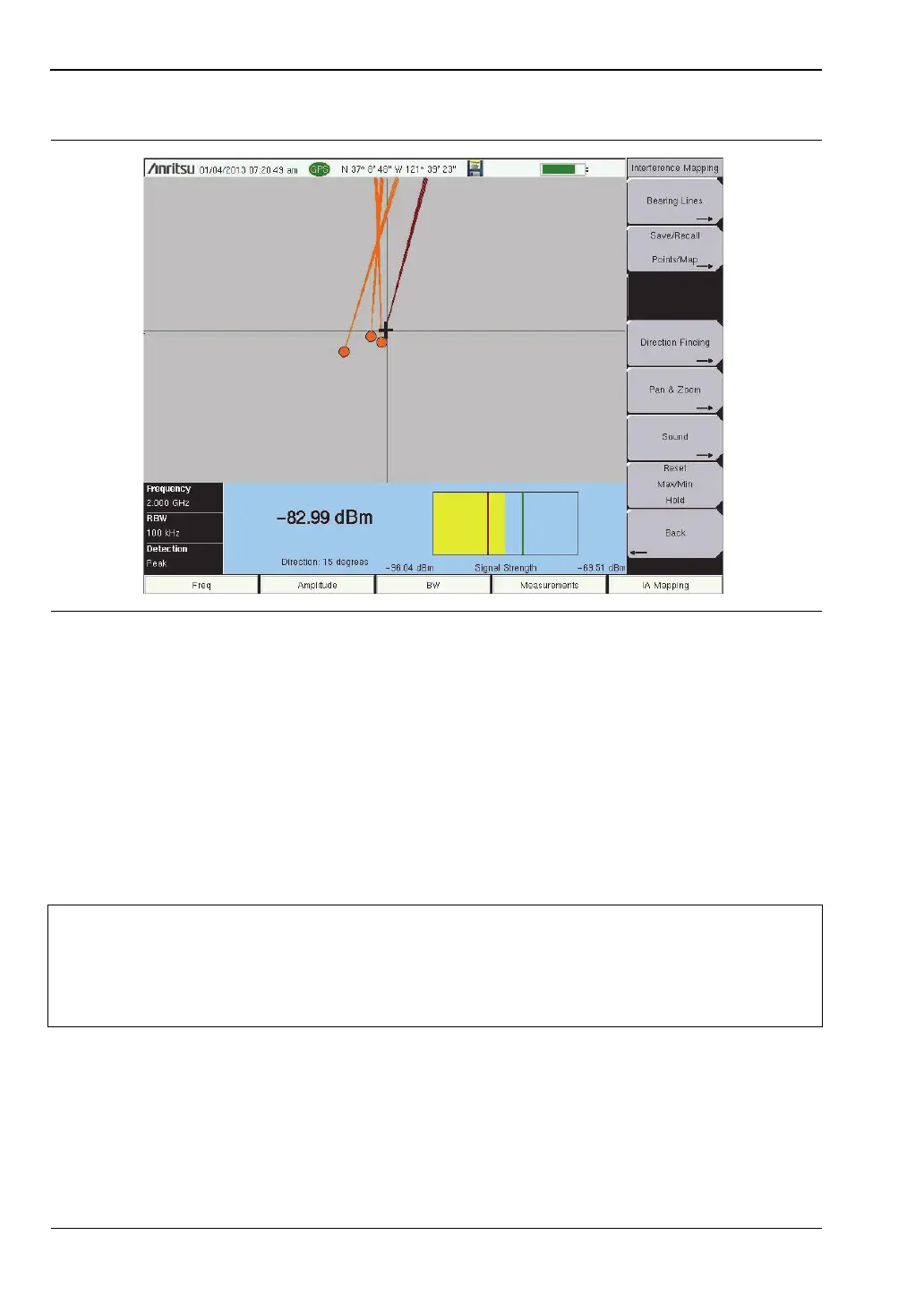
5. Map the interfering signal.
Once you have the GPS signal, directional antenna, and the GeoEmbedded map or the default
grid map loaded on the instrument, you can start locating interfering signals. The plus sign
shows the current location on the screen.
A. Press the Measurements main menu key then the Interference Mapping submenu key.
B. Use the directional antenna to locate the bearing of the strongest signal. Rotate the
knob on the Anritsu instrument until the red line on the display is aligned with the
direction of the interfering signal. Under the Bearing Lines submenu, press the
Save Current Bearing Location & Direction key to save the current location and direction.
C. Move to the next location and repeat step 5B. You now have two lines on the screen and
an idea of where the interfering signal is located. Pan & Zoom as needed (if using an
AZM map). An example of interference mapping where approximate location of the
interferer is determined is shown in Figure 3-8 on page 3-13.
Figure 3-7. Locating an Interfering Signal with the Default Grid
Note
A compass may be helpful to determine the bearing of the strongest Antenna
signal. Use the rotary knob on the instrument to match the direction (shown at the
bottom of the display) of the vector on the screen to the compass bearing (or a
landmark) of the strongest signal before pressing the Save Current Bearing
Location & Direction submenu key.
ООО "Техэнком" Контрольно-измерительные приборы и оборудование www.tehencom.com
 Loading...


