Interference Analyzer (Option 25) 3-8 Interference Mapping
Spectrum Analyzer MG PN: 10580-00349 Rev. H 3-13
6. Save the Mapping Information.
Refer to “Save the Mapping Information” on page 3-19.
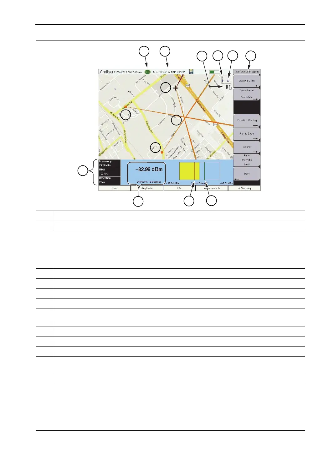
1 Maximum signal level.
2 Minimum signal level.
3 Current readings.
• Power level: Displays the power level at the Anritsu instrument’s receiver.
• Direction: Bearing of the active vector (red). Adjust with the rotary knob on the
Anritsu instrument.
4 Current Anritsu instrument settings.
5 GPS lock icon.
6 Current position.
7 Status Icons. Refer to Figure 6-12 on page 6-18.
8 Zoom level indication (when using .azm maps). Top is maximum zoomed in position.
Bottom is maximum zoomed out position. Refer to “Pan & Zoom Menu” on page 6-17.
9 Current tile location in base map (when using .azm maps).
10 Refer to “Interference Mapping Menu” on page 3-66.
11 Plus sign indicates current position.
12 Previous saved locations and bearings. Existing bearings can be deleted. Refer to
“Bearing Lines Menu” on page 3-67.
13 Approximate location of the interfering signal.
Figure 3-8. Interference Mapping Overview
ООО "Техэнком" Контрольно-измерительные приборы и оборудование www.tehencom.com
 Loading...


