25
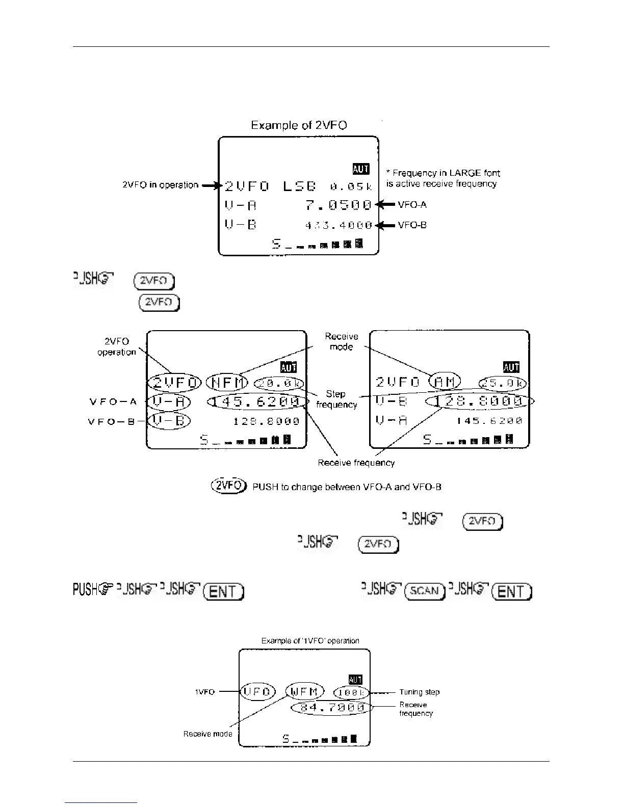
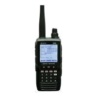
In 2VFO mode both VFO frequencies are displayed in parallel format on the LCD, one above the other.
The ‘
active
’ VFO (the one which is currently receiving) is displayed using a large font centrally on the
LCD, the ‘
standby
’ VFO is shown on a lower line using a smaller font size (when using VFO SCAN it is
possible for the lower line frequency to be active, in this case a larger text size is employed for clarity).
the key to first select ‘
VFO mode
’ (should the receiver be scanning or searching etc).
Each time the key is pushed VFO “V-A” and VFO “V-B” alternate between active and standby.
The first time you enter a frequency via the numeric keypad, it is best to the key to
place the receiver in a known state of operation. the key so the “V-A” becomes the
active VFO (upper and largest of the two frequency readouts). This condition is referred to as ‘
2VFO
’
mode with VFO-A active and VFO-B as standby. If you find the twin frequency display confusing,
or use the key sequence
(while no signal is present) so that only a single frequency readout is displayed, this is referred to as
‘
1VFO
’ mode. Both 1VFO and 2VFO modes may be referred to simply as VFO mode or
manual mode
.
Section 3-2