Manual, F/T Sensor, Data Acquisition (DAQ) Systems
Document #9620-05-DAQ.indd-20
Pinnacle Park • 1031 Goodworth Drive • Apex, NC 27539 • Tel: 919.772.0115 • Fax: 919.772.8259 • www.ati-ia.com • Email: info@ati-ia.com
46
6. Remove the back panel with the backplane board attached.
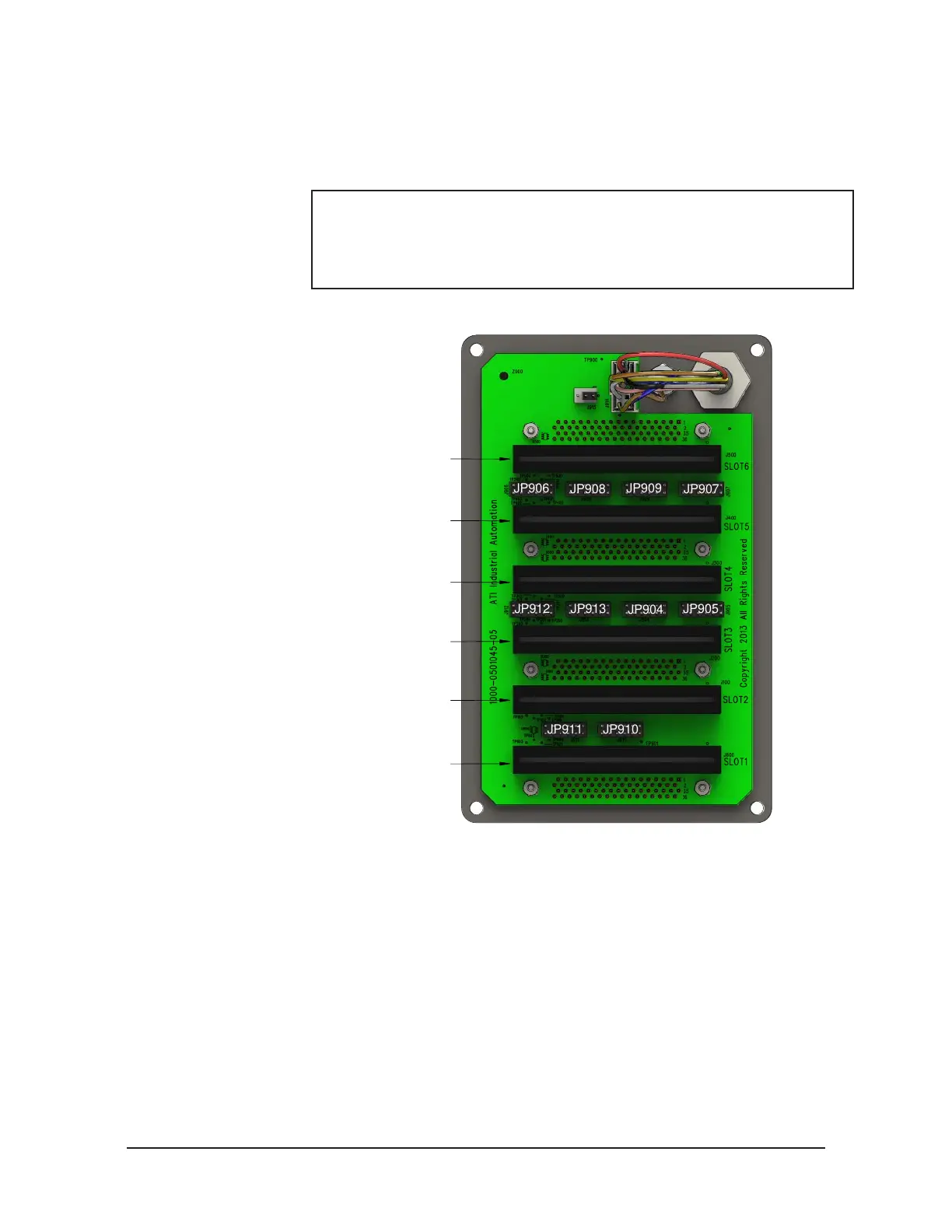
7. Remove the jumpers from the bag supplied with the IFPSMC box. Jumpers can be
installed for all the DAQ boards that are not installed in the IFPSMC box. Refer to
Figure 4.18.
NOTICE: Do not install jumpers for DAQ boards that are installed in the
IFPSMC box. Only install the associated jumpers for slots without a DAQ
board installed. The jumpers make available the signals not used for
the Transducer signals, this will override the signals from the transducer
connectors. Refer to Table 4.11 and Table 4.12 for signal available.
Figure 4.18—Install 12 Pin Jumpers on the IFPSMC Backplane
JP908
JP904
JP905
JP913JP912
JP907
JP906
JP909
JP910JP911
If an IFPS Card is not installed in Slot 1 (TC1)
Install Jumpers on JP910 and JP911
If an IFPS Card is not installed in Slot 2 (TC2)
Slot 2 has no associated Jumpers
If an IFPS Card is not installed in Slot 3 (TC3)
Install Jumpers on JP912 and JP913
If an IFPS Card is not installed in Slot 4 (TC4)
Install Jumpers on JP904 and JP905
If an IFPS Card is not installed in Slot 5 (TC5)
Install Jumpers on JP906 and JP907
If an IFPS Card is not installed in Slot 6 (TC6)
Install Jumpers on JP908 and JP909
8. Attach the back panel to the IFPSMC box, secure with the (4) M4 pan head screws.
9. Connect the DAQ boards to the backplane by pushing them in until they seat into
the backplane connector. Connect all the DAQ boards disconnected in step 4.
10. Carefully rotate the front panel back into place on the IFPSMC box and secure
using the (4) M4 pan head screws,
11. Connect the male connector on the transducer cable to the appropriate connector
on the front of the IFPSMC box. Note: The serial number label on the transducer
must match the serial number label on the IFPSMC Box connector the transducer is
plugged into. Refer to Figure 4.9.
12. Reconnect the power supply and DAQ cables to the back of the IFPSMC box.
Refer to Figure 4.25.
13. After the procedure is complete, resume normal operation.
 Loading...
