Operating Instructions Xenotest
®
150 S+
40
6.9 RS 232 interface set-up
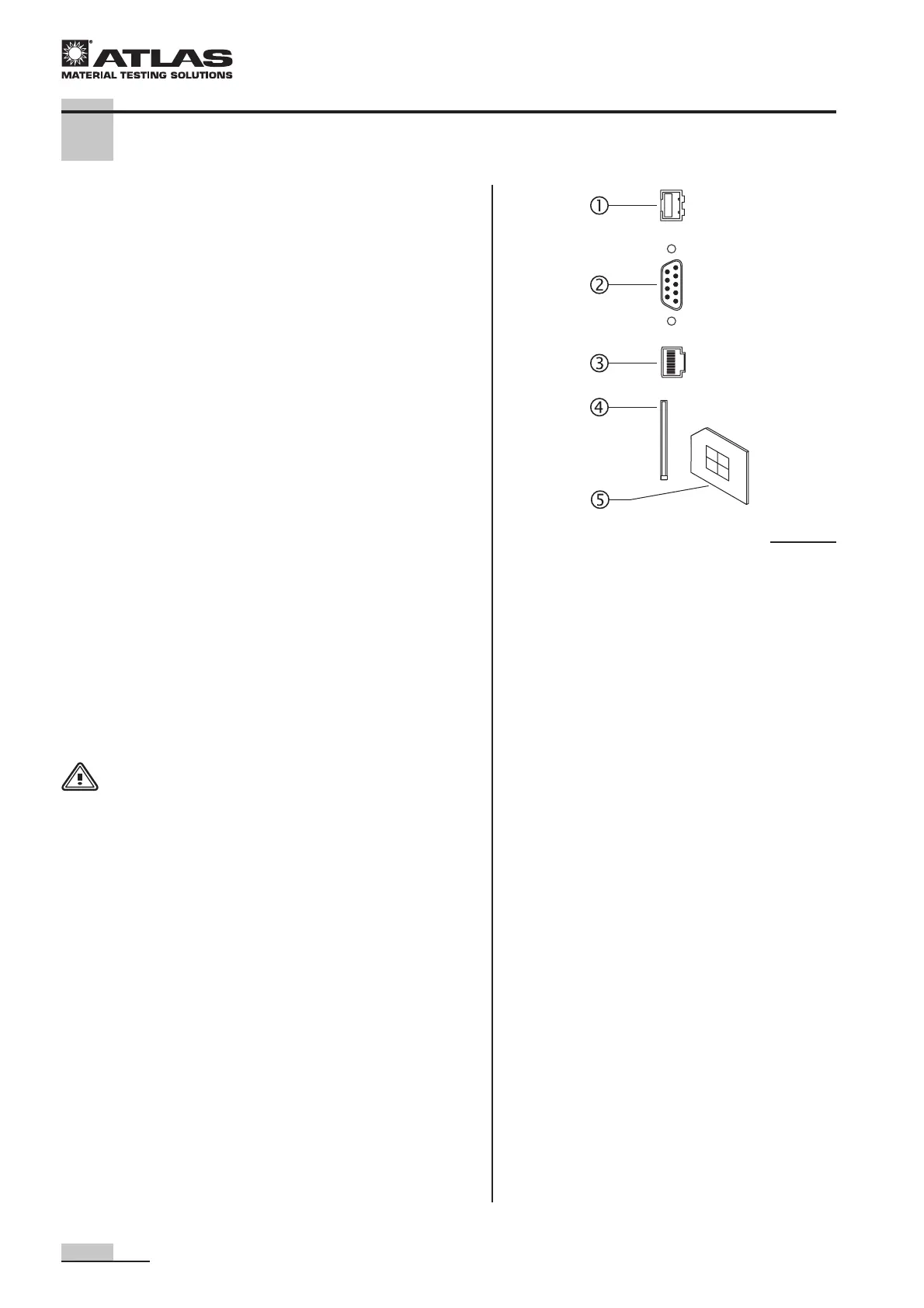
Fig. 26: The instrument is equipped with for interfaces for
data communication with external systems.
Network connection
11
11
1:
Via the protocol "Integrated Fast Ethernet Controller"
(3C905C-TX-compatible), the test instrument can be inte-
grated into a network. Available only with later software
version.
Serial interface
22
22
2:
The RS232 interface allows the output of measuring data to
a computer during a running test program. Available only
with later software version.
USB interface
33
33
3:
Data interface in accordance with USB 2 standard. This in-
terface allows the output of measuring data to a computer
during a running test program. Available only with later soft-
ware version.
Slot
44
44
4 for memory chip
55
55
5:
For updating already installed instrument software, loading
new check programs or downloading measuring and test
data.
6.10 Power supply connection
WARNING - Electric shock!
Contact with voltage-carrying components
may cause a lethal electric shock.
Prior to connecting the instrument to the
power supply system, check plug and po-
wer supply cable for possible damage.
Do not use damaged components for a
connection to the power supply system!
The Xenotest
®
150 S+ is connected to a mains voltage of
230 V ± 10 %, 50/60 Hz.
The power supply connection is made through a grounding
plug:
(1P, N, PE) or (2P, PE), CEE (32A, 3 poles, 6h).
The power supply system must be properly fused.
6 Start-up
Fig. 26
 Loading...