16
Operating Instructions Xenotest
®
150 S+
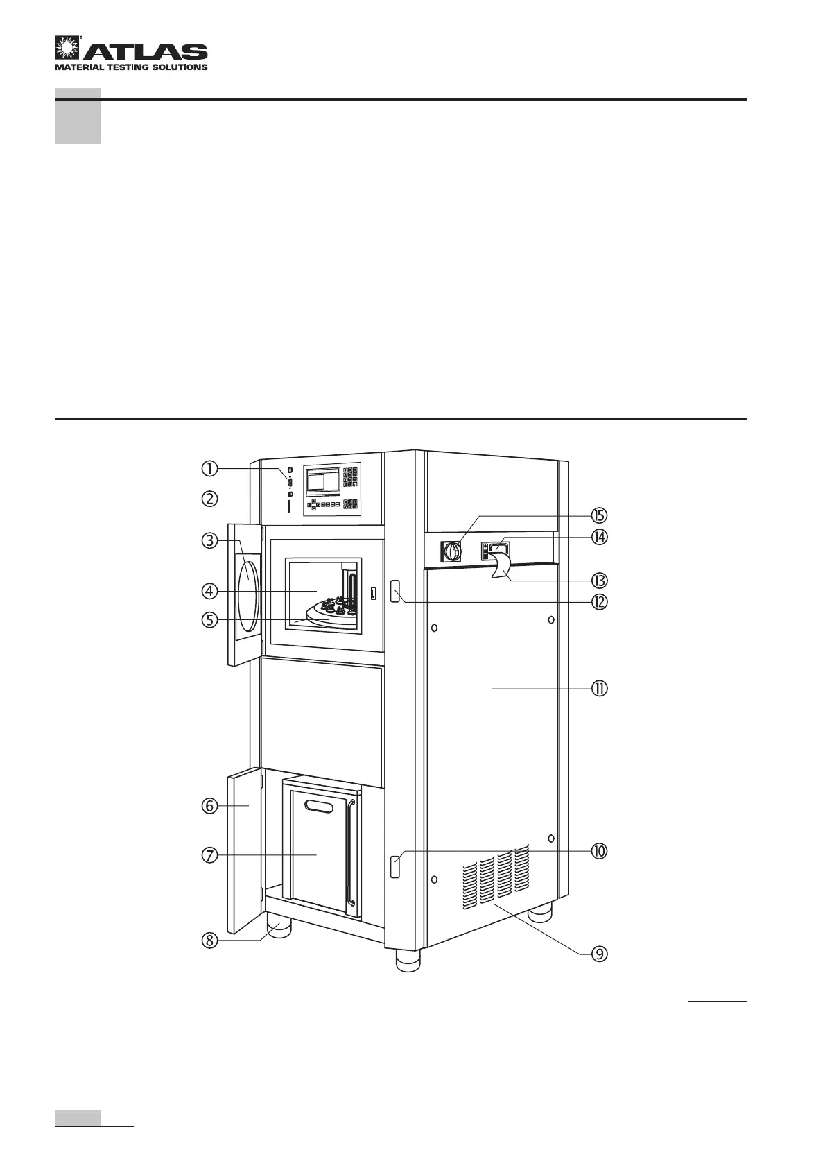
4.1 Front and right view
Front view, Fig. 3:
1 Communication ports
2 Operating panel with touch screen
3 Test chamber door with viewport
4 Test chamber with rotating system and
irradiation unit
5 Rotating system with sample holder bracket
6 Door to water supply system
7 Reservoir for treated water
8 Height-adjustable stand
Right view, Fig. 3:
9 Air inlet opening for lamp cooling and cooling of
electrical components
A Water supply system door release
B Door to electrical supply unit
C Test chamber door release
D Print output to paper strip (optional printer)
E Optional printer for test data output
F Main switch for switching the instrument on and off
4 Description of the instrument
Fig. 3
 Loading...